Optical head with lasers and mirrors in a recess formed in a substrate

a technology of optical head and recess, which is applied in the direction of optical beam source, semiconductor laser, instruments, etc., can solve the problem of unavoidable increase in the number of optical head components

Inactive Publication Date: 2005-06-09
HITACHI CONSUMER ELECTRONICS CORP
View PDF18 Cites 6 Cited by
  • Summary
  • Abstract
  • Description
  • Claims
  • Application Information

AI Technical Summary

Benefits of technology

[0004] It is an object of the present invention to improve the above-mentioned problems. More particularly, it is an object of the invention to provide a breakthrough for reducing the size and thickness of the whole of a driver capable of recording and reproducing information for various optical discs.
[0006] According to the second means adopted in the present invention, index marks for alignment are affixed onto both a silicon substrate with photodetectors formed thereon and semiconductor lasers, their images are formed on a photoelectric conversion surface such as CCD and are inputted into a computer, followed by calculation of centroids of the marks and alignment. The centroid calculation permits ensuring a submicron order of alignment accuracy.
[0011] According to the seventh means adopted in the present invention, an amplifier for electrically amplifying light currents generated by photodetectors is formed monolithically on a silicon substrate with the photodetectors formed thereon, and when semiconductor lasers are soldered onto the silicon substrate with a tilted mirror formed thereon and with an alignment index mark affixed thereto, a material having a high thermal conductivity is interposed between the semiconductor lasers and the silicon substrate for the purpose of widely diffusing the heat generated from the semiconductor lasers.

Problems solved by technology

Thus, an increase in the number of components in the optical head will be unavoidable.

Method used


Image

  • Optical head with lasers and mirrors in a recess formed in a substrate
  • Optical head with lasers and mirrors in a recess formed in a substrate
  • Optical head with lasers and mirrors in a recess formed in a substrate

Examples


Embodiment Construction

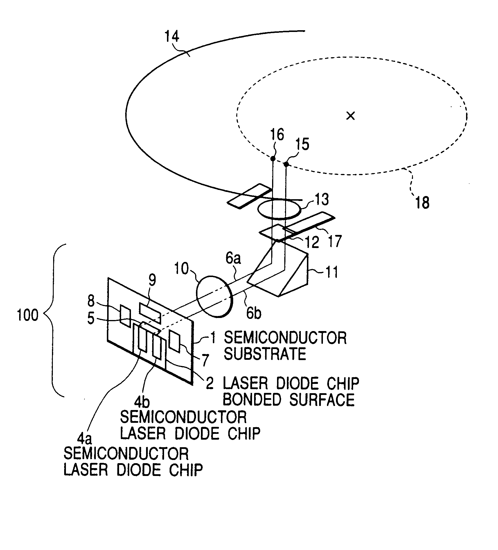
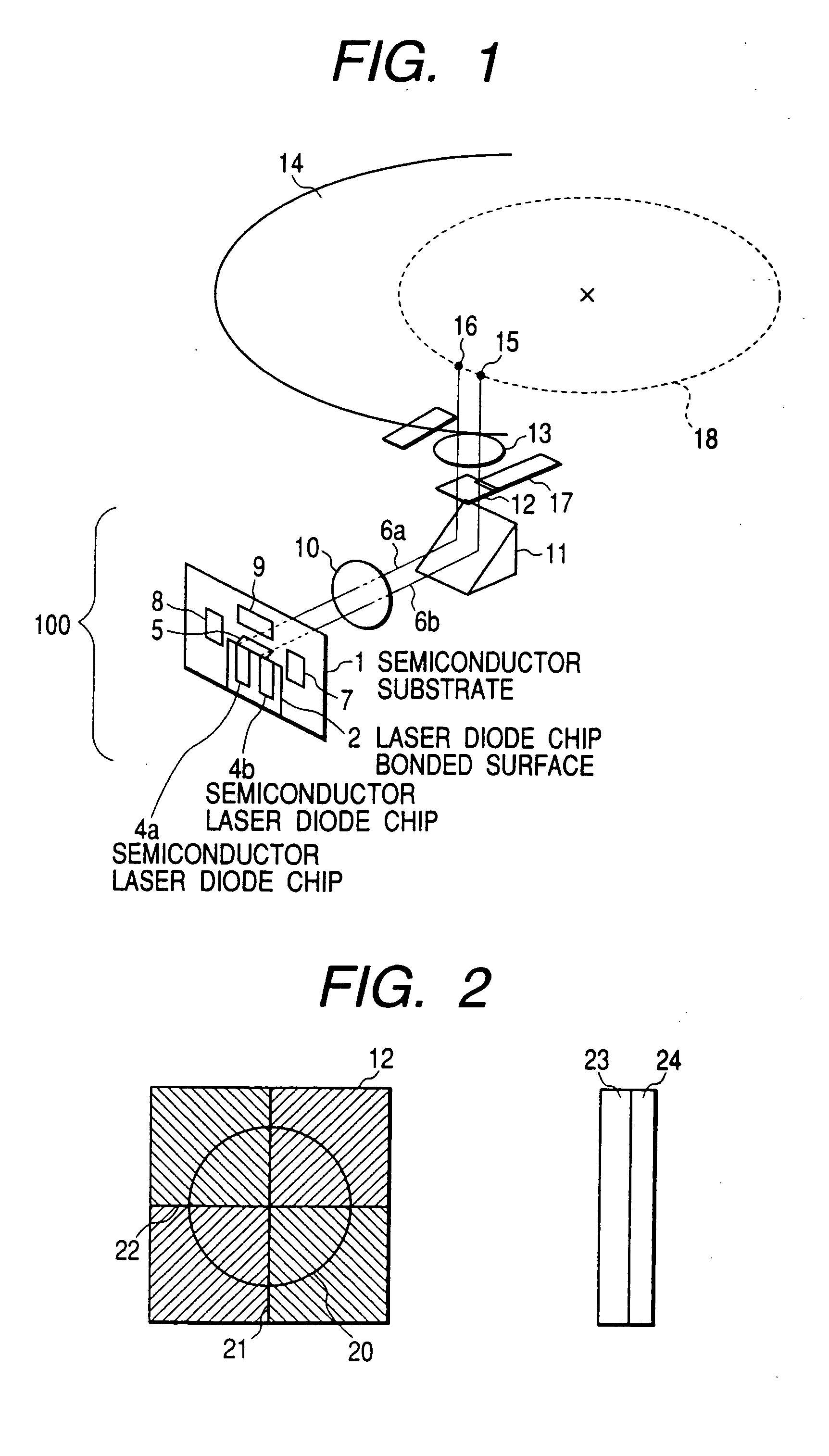
[0026]FIG. 1 illustrates the configuration of an optical head according to the present invention. An integration module 100 comprises a semiconductor substrate 1, semiconductor laser chips 4a and 4b, a reflecting mirror 5, and photodetectors 7,8 and 9. Laser beams, indicated at 6a and 6b, from the integration module 100 are collimated by a collimator lens 10, then pass through a mirror11 and a grating plate 12, and reach an objective lens 13, whereby the beams are formed as spots 15 and 16 on a surface of an optical disc 14. The objective lens 13 comprises plural such lenses according to wavelengths of the semiconductor lasers or a single lens capable of focusing beams of different wavelengths. The objective lens is focused onto a recording surface of the optical disc in accordance with a rotational movement of the same disc by means of an actuator 17 and performs tracking, that is, follows a recording track 18 formed on the disk surface. Thus, in accordance with ON or OFF of the se...


PUM

PropertyMeasurementUnit
wavelengthsaaaaaaaaaa
thicknessaaaaaaaaaa

Abstract

An integrated optical head records and reproduces information to and from optical discs of different types, including CD and DVD, with use of a single information recording / reproducing apparatus. The optical head has a plurality of semiconductor lasers of different wavelengths integrated by index alignment onto a substrate formed with an optoelectric integrated circuit, photodetection patterns, and a reflecting mirror.

Description

BACKGROUND OF THE INVENTION [0001] The present invention relates to a laser module or an optical head. For example, the invention relates to a laser module or an optical head in which a semiconductor laser beam modulated by an electric signal is applied to an optical information recording medium such as an optical disc to record information on the medium or reproduce a recorded information from the medium. In particular, the invention is concerned with a laser module or an optical head each using a plurality of light sources. [0002] In an optical head mounted on an optical disc recording and read-out apparatus, light sources and photodetectors are separated from each other. Consequently, it is impossible to attain a high fabrication integration density of light sources and photodetectors and hence it has so far impossible to attain the reduction in size and thickness of the entire optical disc apparatus. In an effort to solve this problem, a hybrid integration of photodetectors and ...

Claims


Application Information

Patent Timeline
Patent Type & Authority Applications(United States)
IPC IPC(8): G11B7/00G11B7/12G11B7/125G11B7/22G11B21/00H01S3/00H01S5/022H01S5/0683H01S5/40
CPCG11B7/1205G11B7/1275G11B7/22G11B2007/0006H01S5/4087H01S5/02252H01S5/02292H01S5/02296H01S5/0683H01S5/02216G11B7/123H01S5/0231H01S5/02255H01S5/02257H01S5/02326G11B21/00
Inventor TATSUNO, KIMIOTOKUDA, MASAHIDESANO, HIROHISATANAKA, TOSHIAKISHIMANO, TAKESHINAKAMURA, SHIGERUMAEDA, TAKESHIARIMOTO, AKIRA
Owner HITACHI CONSUMER ELECTRONICS CORP
Why Eureka
Try Eureka