Rotor blade pitch control assembly

a technology of rotor blades and assembly parts, applied in the direction of machines/engines, liquid fuel engines, transportation and packaging, etc., can solve the problems of affecting the performance of rotor blades, affecting the pitch of rotor blades, and requiring a relative large servo flap, etc., to achieve small forces and deflection, enhance rotor aerodynamic performance, and reduce vibration

Active Publication Date: 2005-06-09
SIKORSKY AIRCRAFT CORP
View PDF9 Cites 21 Cited by
  • Summary
  • Abstract
  • Description
  • Claims
  • Application Information

AI Technical Summary

Benefits of technology

[0006] The trailing edge servo flap is located outboard of the trailing edge flap in the span wise direction, relative to the root end of the blade. The servo flap may also be off set from the trailing edge flap in the chord wise direction as measured from the main rotor blade leading edge. The servo flap, if present, is located upon a trailing edge servo flap arm. The servo flap arm is linked to the trailing edge flap and pitches about a trailing edge servo flap arm pitch axis. The chord wise off set of the servo flap provides a moment arm to transfer a pitching moment from the servo flap to the trailing edge flap. The span wise offset of the servo flap relative to the trailing edge flap provides a significant increase in aerodynamic force available to pitch the main rotor blade. The cause of this force amplification is a result of locating the servo flap out board of the trailing edge flap in the span wise direction. By so doing, the servo flap operates in a higher speed relative flow environment as induced by the rotational motion of the main rotor blade.
[0009] The mechanical advantage that is realized by offsetting the servo flap from the trailing edge flap in the span wise and / or combined span wise and chord wise directions provides the necessary aerodynamic force amplification required to deflect the trailing edge flap, that in turn results in pitching of the main rotor blade.
[0010] The present invention, therefore, provides a rotor blade pitch control system utilizing an uncomplicated and lightweight trailing edge servo flap that requires minimal, if any, transfer of a motive force through a rotational interface. Furthermore, because smart actuators can be made to deflect at frequencies greater than the rotational frequency of the rotor, but can deliver only small forces and deflections compared to larger and heavier actuators, the present invention enables the use of small, light actuators for high frequency rotor blade control. The ability to tune the smart / active control actuators in phase and amplitude to provide deflections at required blade locations also generates favorable blade motions to enhance rotor aerodynamic performance, reduce vibration and reduce noise.

Problems solved by technology

A major disadvantage of conventional servo flaps is that a relatively large servo flap is usually required to produce the forces and moments necessary to control the pitch of the main rotor blade.
These servo flaps require powerful actuators, which may be relatively heavy and mechanically complex.
Actuator size may also be a limitation as the actuators must be located within the restricted space inside the rotor blade.
Otherwise, significant drag and power penalties accrue if the actuators are exposed to the airflow.
Redundancy requirements and the necessity of connecting control armatures and linkages or transferring a motive fluid via hydraulics through a rotational interface to the actuator may further complicate conventional servo flap operation.

Method used


Image

  • Rotor blade pitch control assembly
  • Rotor blade pitch control assembly
  • Rotor blade pitch control assembly

Examples


Embodiment Construction

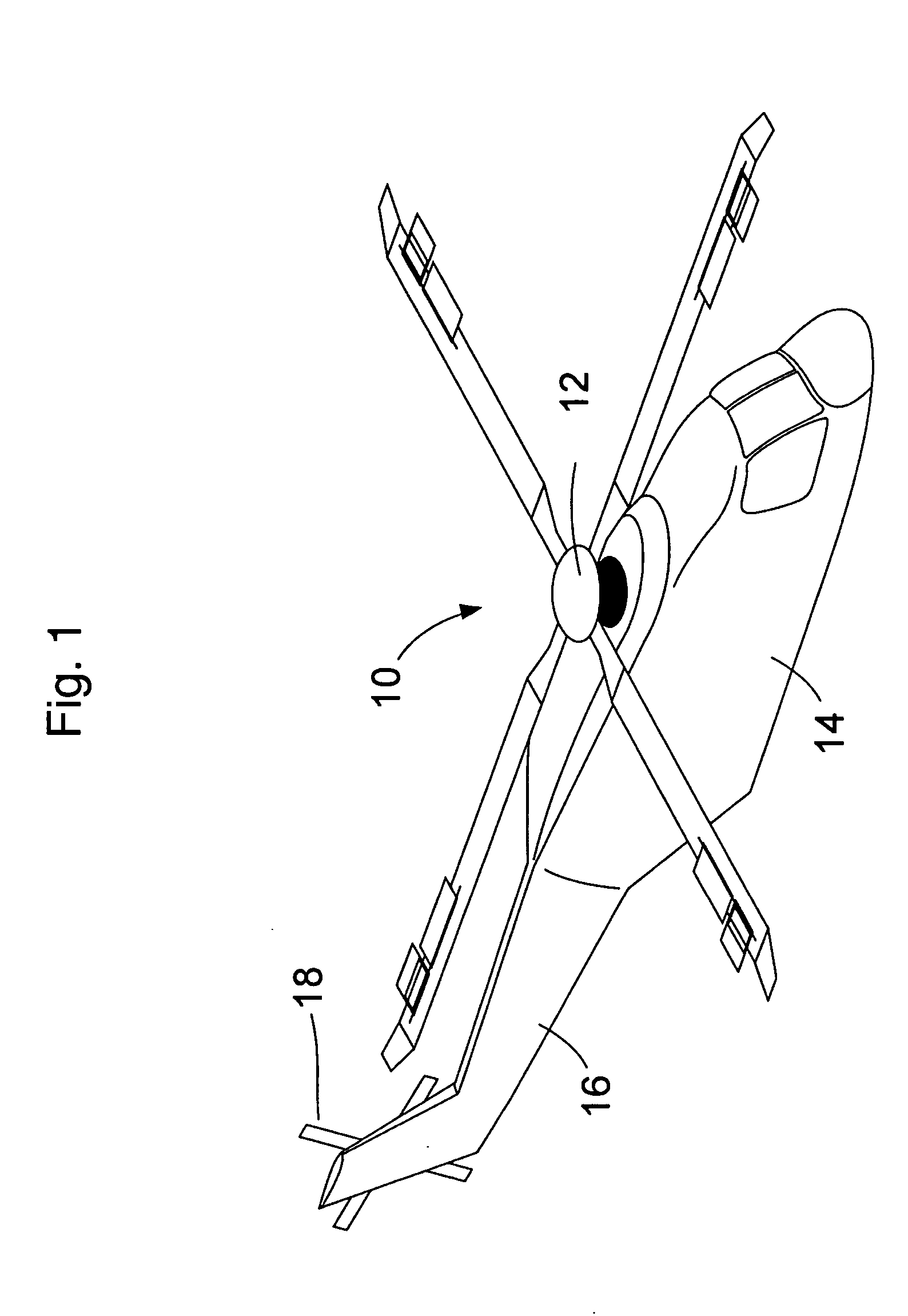
[0019]FIG. 1 schematically illustrates a rotary wing aircraft 10 having a main rotor assembly 12. The aircraft 10 includes an airframe 14 having an extending tail 16 which mounts an anti-torque rotor 18. Although a particular helicopter configuration is illustrated in the disclosed embodiment, other configurations such as side-by-side, tilt rotor, coaxial, and tandem designs and configurations will also benefit from the present invention.

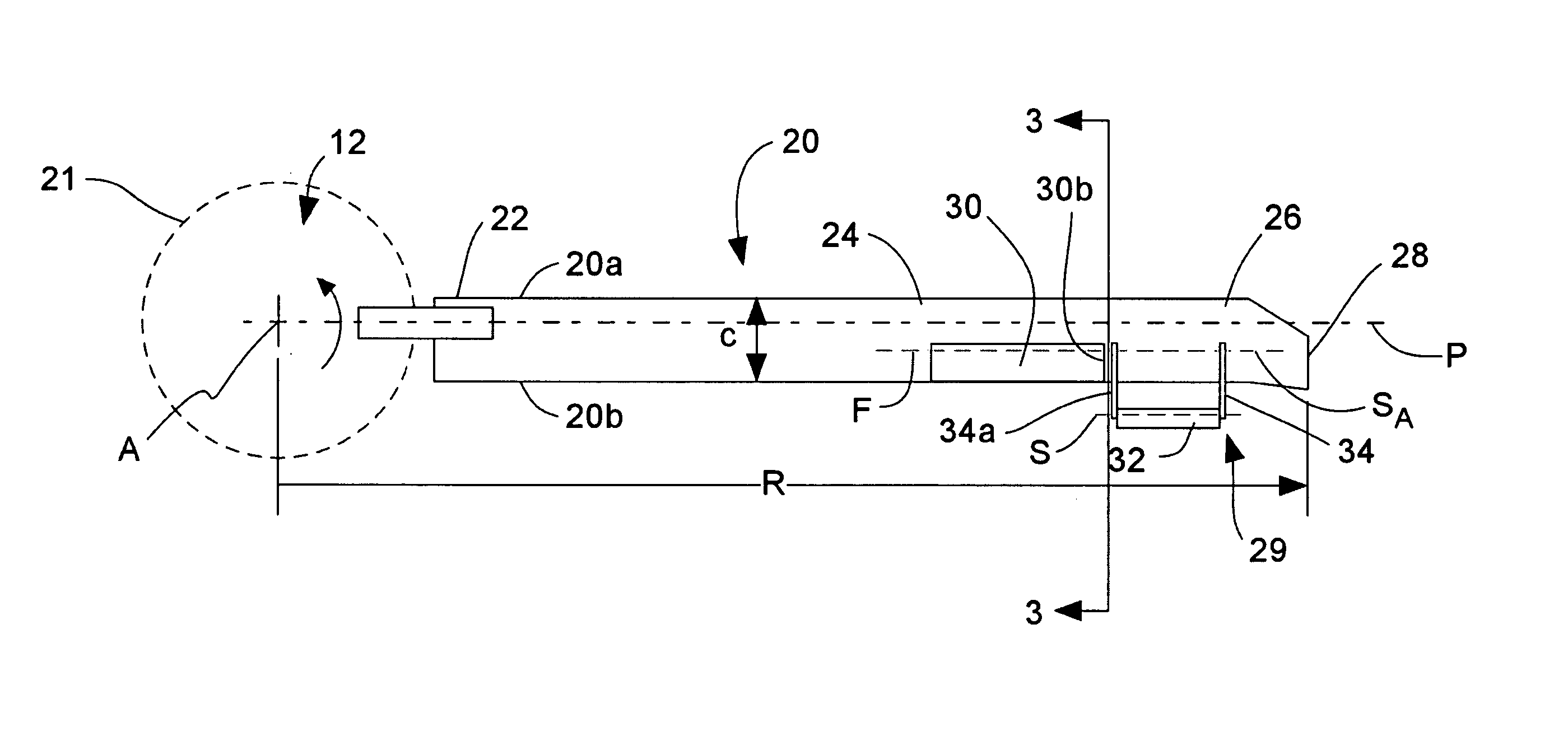
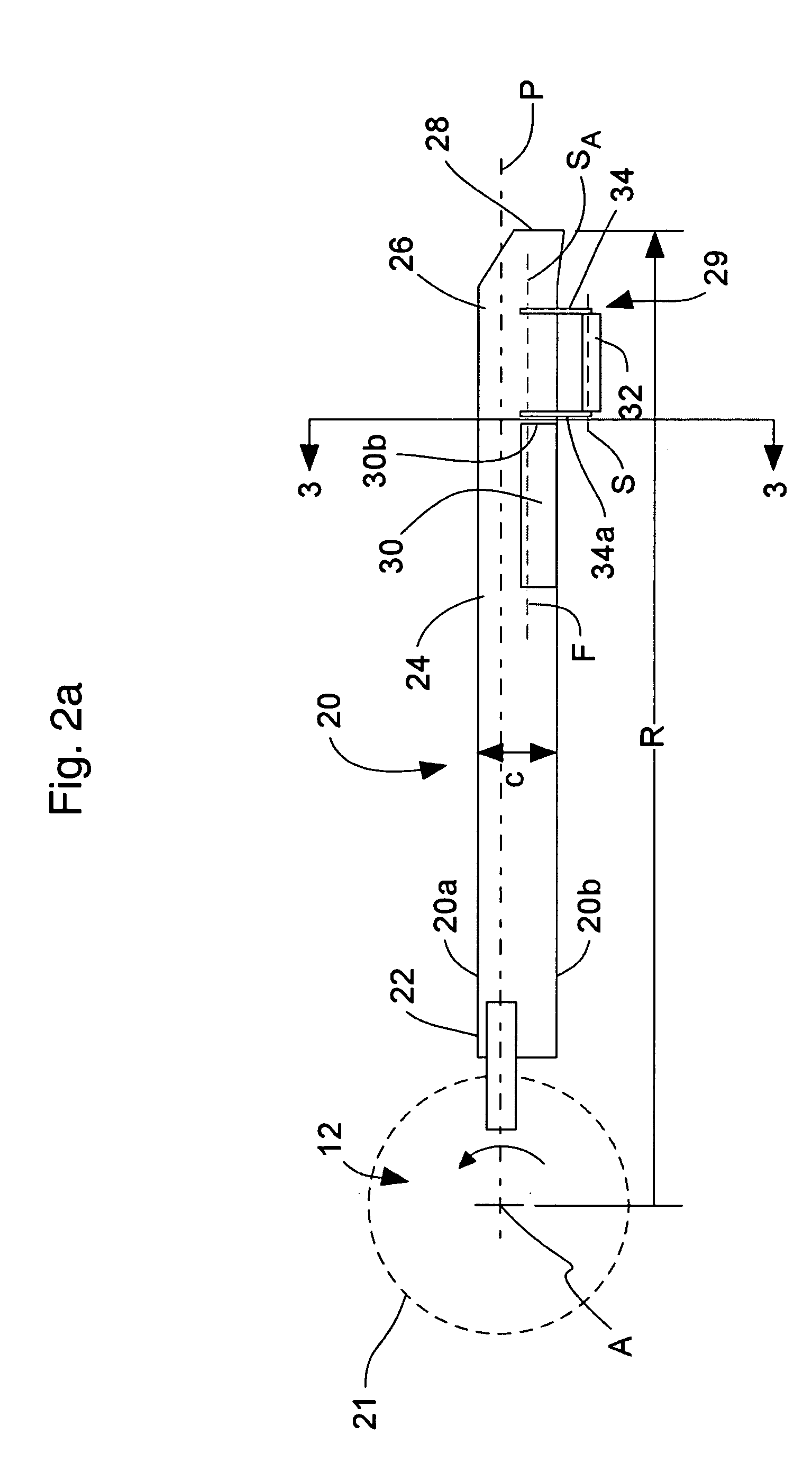
[0020] Referring to FIG. 2a, a rotor blade assembly 20 (only one illustrated) that is part of a rotor head assembly 12 includes an inboard section 22, an intermediate section 24, and an outboard section 26. The inboard, intermediate, and outboard sections 22, 24, 26 define the span of the main rotor blade 20. The blade sections 22, 24, 26 define a blade radius R between the axis of rotation A and a blade tip 28.

[0021] The blade root portion 22 is attached to the rotor assembly 12 for rotating the rotor blade 20 about the axis of rotation A. The ro...


PUM


Abstract

A rotor blade assembly provides a pitch control assembly to pitch the rotor blade about a rotor blade pitch axis. The pitch control assembly includes a trailing edge flap and a trailing edge servo flap that extend from the trailing edge of the rotor blade. The trailing edge flap is offset in the span wise direction relative to the trailing edge flap. The trailing edge servo flap is located upon a trailing edge servo flap arm linked to the trailing edge flap. To pitch the rotor blade, the trailing edge servo flap is pitched in a direction opposite the desired pitch direction of the trailing edge flap.

Description

BACKGROUND OF THE INVENTION [0001] The present invention relates to pitch control of a rotor blade assembly, and more particularly to a rotor blade with a trailing edge flap driven by a servo flap that is offset relative to the trailing edge flap along the blade span wise direction. [0002] Some rotary wing aircraft utilize servo flaps for pitch positioning of a main rotor blade. The servo flaps are often located aft of the trailing edges of their associated rotor blades. Such trailing edge servo flaps, in combination with their associated rotor blades, are essentially stable. That is, when the servo flap is moved about its own pitch axis, the blade moves (pitches) toward a balanced condition at which the aerodynamically induced pitch changing moment that is applied to the blade by the servo flap is opposed by the aerodynamic pitch changing moment experienced by the blade. [0003] A major disadvantage of conventional servo flaps is that a relatively large servo flap is usually require...

Claims


Application Information

Patent Timeline
Patent Type & Authority Applications(United States)
IPC IPC(8): B64C9/10B64C27/615
CPCB64C9/10Y02T50/34B64C27/615Y02T50/30
Inventor BAGAI, ASHISH
Owner SIKORSKY AIRCRAFT CORP
Why Eureka
Try Eureka