
Perpendicular magnetic recording medium

a magnetic recording medium and perpendicular technology, applied in data recording, thin material processing, instruments, etc., can solve the problems of long time period required for the formation of soft magnetic backing layers having the above required thickness, difficult to greatly reduce the grain size of magnetic particles, and increase production costs, etc., to achieve high film deposition rate, easy to obtain, and excellent product quality

Inactive Publication Date: 2005-06-09
FUJITSU LTD
View PDF5 Cites 7 Cited by
  • Summary
  • Abstract
  • Description
  • Claims
  • Application Information

AI Technical Summary

Benefits of technology

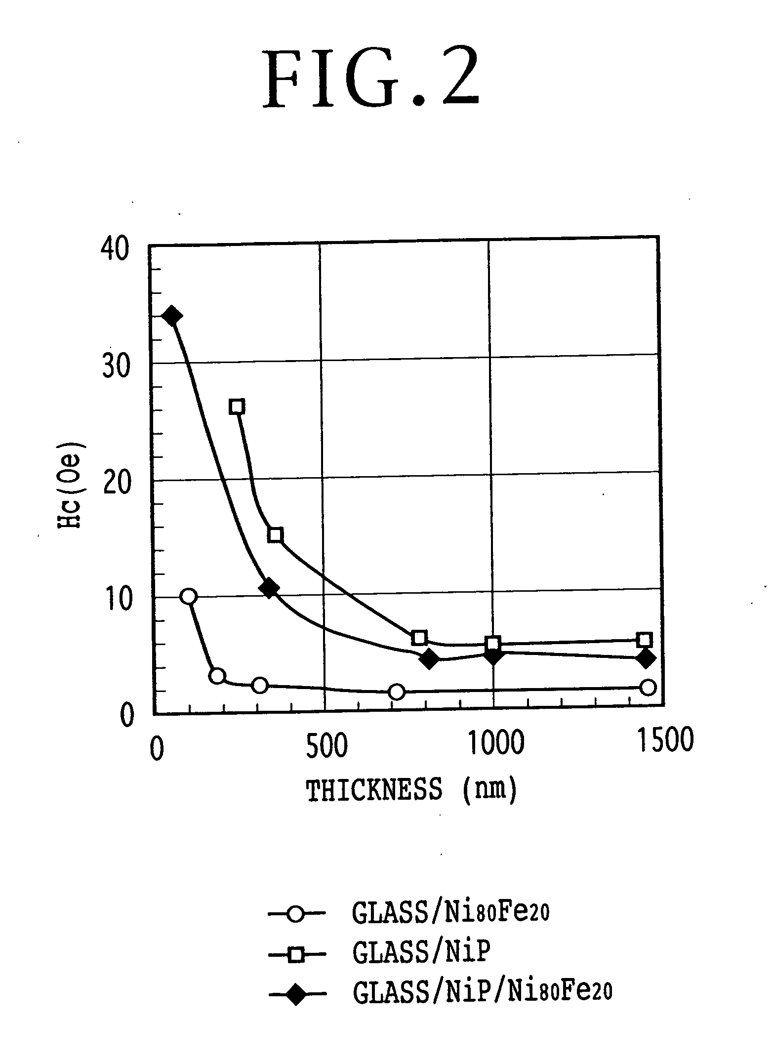
The present invention provides a perpendicular magnetic recording medium that can be mass-produced at a relatively low cost. The medium includes a substrate, a metal base layer, a soft magnetic layer, and a magnetic recording layer. The soft magnetic layer is formed by electroless plating, which has advantages such as high deposition rate and stable coercivity. The use of a metal film as the base layer can reduce the dependence of coercivity upon the thickness of the electroless plated film. The invention allows for the production of a perpendicular magnetic recording medium with low coercivity and stable soft magnetic characteristics.

Problems solved by technology

In a conventional recording method referred to as an in-plane (longitudinal) recording method, it is difficult to greatly reduce the grain size of magnetic particles because of thermal instability.
If the soft magnetic backing layer is formed by sputtering for use in deposition of each layer in a conventional magnetic recording medium, a very long period of time is required for the formation of the soft magnetic backing layer having the above required thickness.
As a result, a production cost is increased and mass production becomes difficult.

Method used


Image

  • Perpendicular magnetic recording medium
  • Perpendicular magnetic recording medium
  • Perpendicular magnetic recording medium

Examples


Embodiment Construction

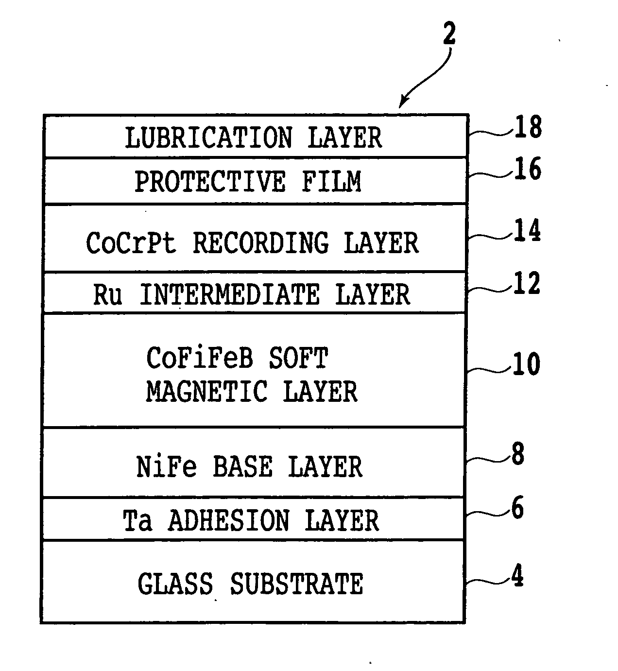
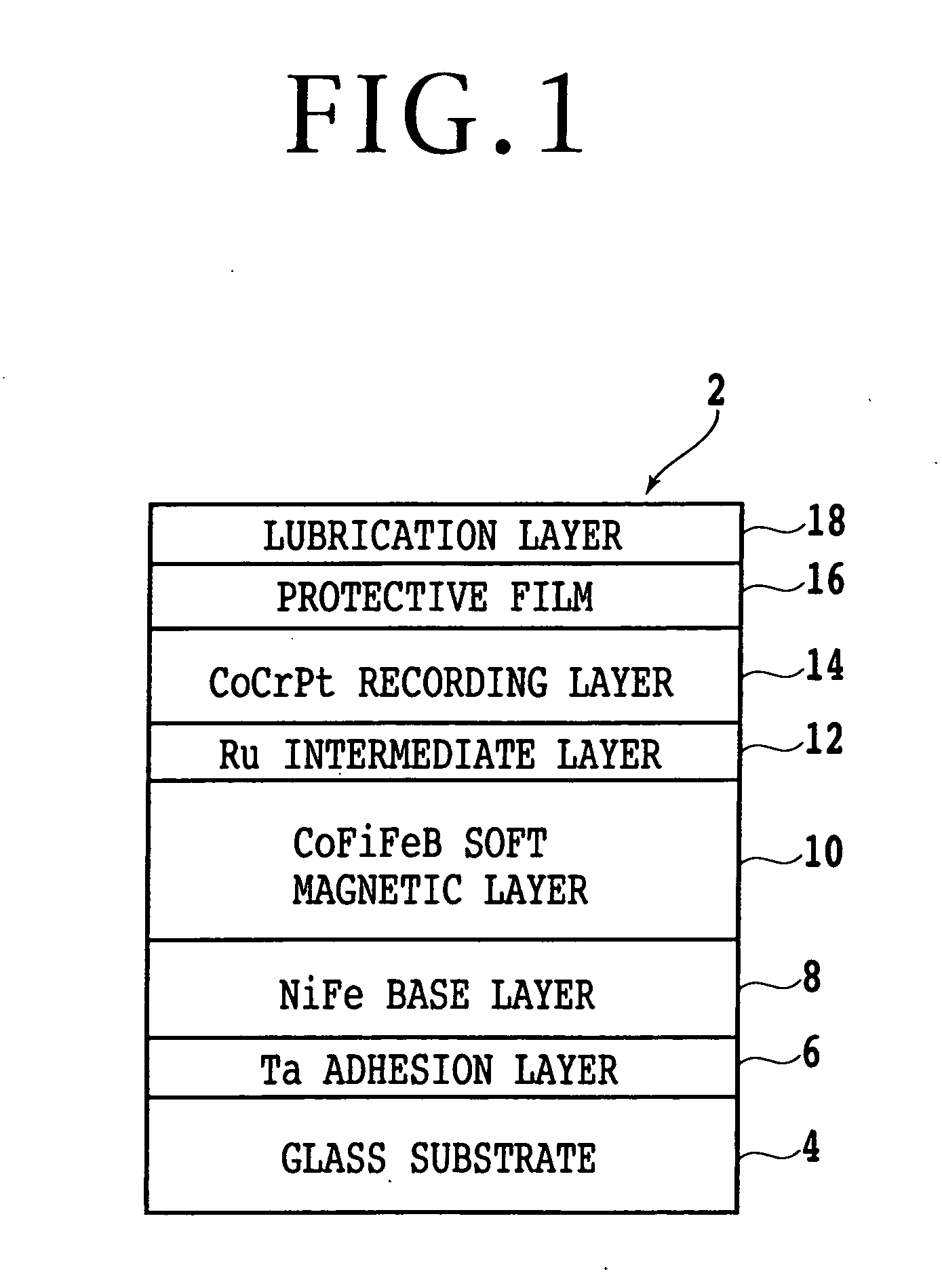
[0018] Referring to FIG. 1, there is shown a schematic sectional diagram showing the configuration of a perpendicular magnetic recording medium 2 according to a preferred embodiment of the present invention. A Ta adhesion layer 6 having a thickness of 1 nm is formed on a 2.5-inch glass disk substrate 4 by sputtering, and an NiFe base layer 8 having a thickness of 50 nm is formed on the Ta adhesion layer 6 by sputtering. The material of the base layer 8 is not limited to NiFe. Preferably, the base layer 8 is formed of an alloy containing at least one element selected from the group consisting of Co, Ni, and Fe. More preferably, the base layer 8 is formed of an alloy selected from the group consisting of Ni80Fe20, Ni50Fe50, FeC, FeAlSi, CoZrNb, and CoTaZr. The thickness of the base layer 8 is preferably set in the range of 10 to 100 nm, more preferably 30 to 70 nm.

[0019] A CoNiFeB soft magnetic backing layer 10 having a thickness of 300 nm is formed on the NiFe base layer 8 by electr...


PUM

PropertyMeasurementUnit
coercivityaaaaaaaaaa
thicknessaaaaaaaaaa
thicknessaaaaaaaaaa

Abstract

A perpendicular magnetic recording medium including a substrate, a metal base layer formed on the substrate, a soft magnetic layer formed on the metal base layer by electroless plating and having an axis of easy magnetization in the in-plane direction of the substrate, and a magnetic recording layer formed on the soft magnetic layer and having an axis of easy magnetization in a direction perpendicular to the surface of the substrate. The metal base layer is formed of an alloy containing at least one element selected from the group consisting of Co, Ni, and Fe, and has a coercivity of 3 oersteds (Oe) or less. The soft magnetic layer has a thickness of 100 to 600 nm.

Description

[0001] This is a continuation of International PCT Application NO. PCT / JP02 / 13711, filed Dec. 26, 2002, which was not published in English.BACKGROUND OF THE INVENTION [0002] 1. Field of the Invention [0003] The present invention relates to a perpendicular magnetic recording medium having a perpendicularly magnetized film as a recording film. [0004] 2. Description of the Related Art [0005] With a reduction in size and an increase in capacity of a magnetic disk drive, it has recently been desired to reduce the grain size of magnetic particles in a recording medium. In a conventional recording method referred to as an in-plane (longitudinal) recording method, it is difficult to greatly reduce the grain size of magnetic particles because of thermal instability. Accordingly, a perpendicular magnetic recording method superior to the in-plane recording method in thermo-magnetic relaxation or the like has been investigated. A general perpendicular magnetic recording method employs a dual-la...

Claims


Application Information

Patent Timeline
Patent Type & Authority Applications(United States)
IPC IPC(8): G11B5/65G11B5/667G11B5/73G11B5/738
CPCG11B5/667Y10T428/265G11B5/7325G11B5/736G11B5/7363G11B5/62
Inventor SHIMIZU, SANAEJOGO, ARATAUZUMAKI, TAKUYATANAKA, ATSUSHI
Owner FUJITSU LTD
Learn More