Method for producing a mask layout avoiding imaging errors for a mask

a mask and mask technology, applied in the field of mask layout avoiding imaging errors, can solve the problems of imaging errors and imaging errors, and achieve the effect of reducing imaging errors as a result of proximity effects

Inactive Publication Date: 2005-06-09
INFINEON TECH AG
View PDF10 Cites 8 Cited by
  • Summary
  • Abstract
  • Description
  • Claims
  • Application Information

AI Technical Summary

Benefits of technology

[0013] In one aspect, the invention provides an improved method of the type specified in the introduction to the effect that imaging errors as a result of proximity effects are reduced even better than before.

Problems solved by technology

It is known that, in lithography methods, imaging errors can occur if the structures to be imaged become very small and have a critical size or a critical distance with respect to one another.
What is more, imaging errors may occur if structures are arranged very closely next to one another.

Method used


Image

  • Method for producing a mask layout avoiding imaging errors for a mask
  • Method for producing a mask layout avoiding imaging errors for a mask
  • Method for producing a mask layout avoiding imaging errors for a mask

Examples


Embodiment Construction

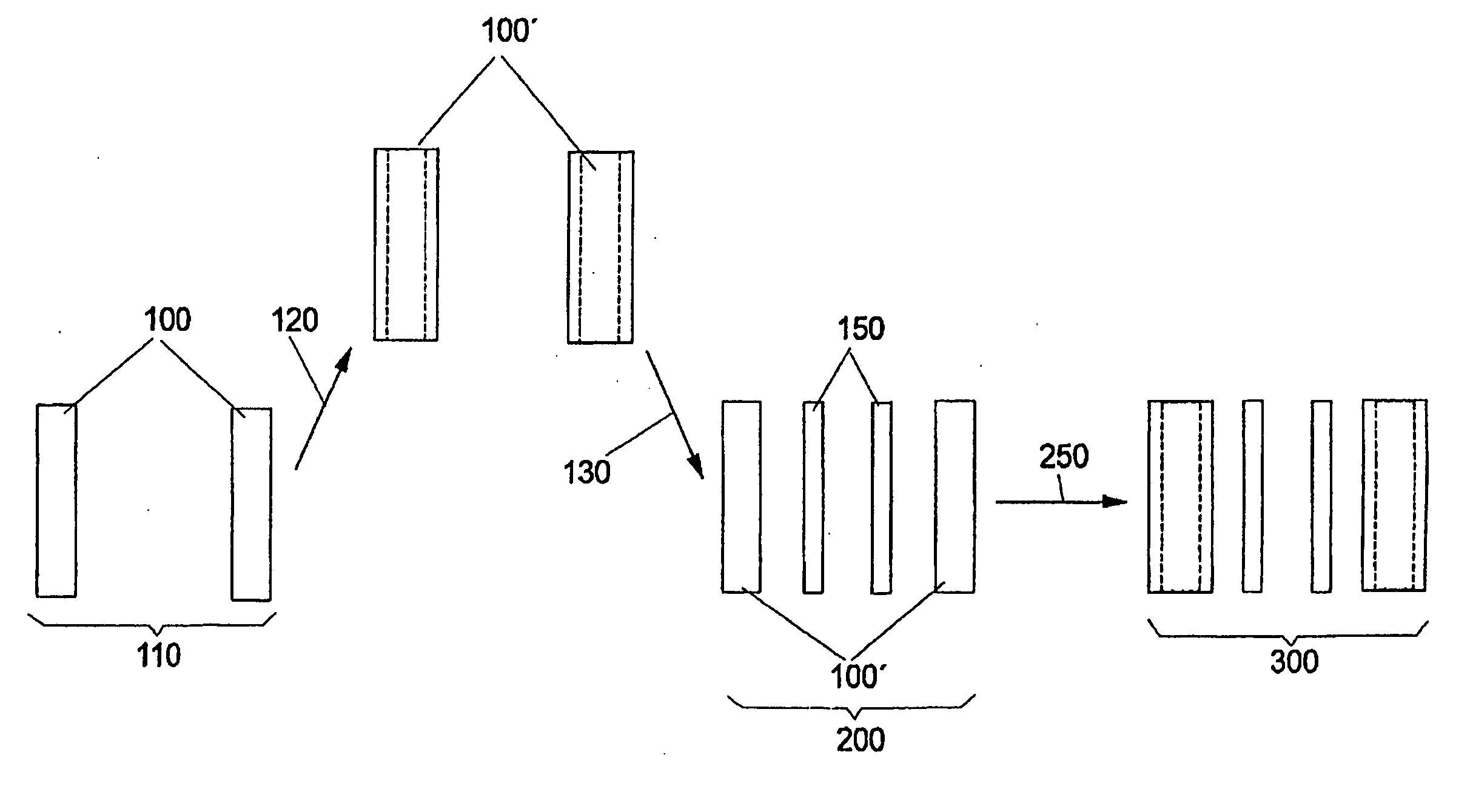
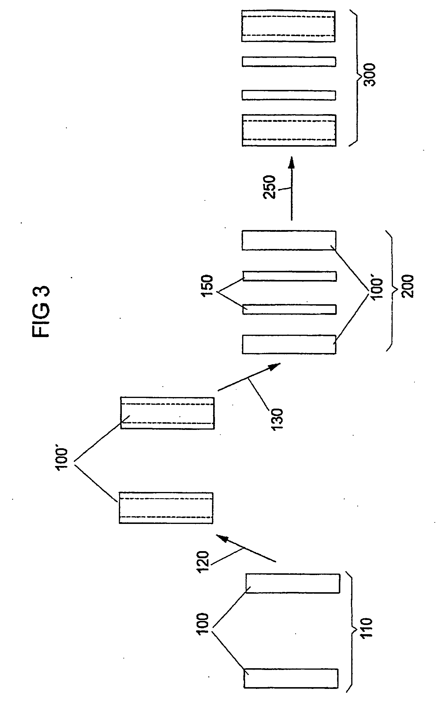
[0067]FIG. 3 reveals a provisional auxiliary mask layout 110 formed by way of example by two vertical lines 100, which is altered in a first modification step—called pre-bias step 120 hereinafter—by widening the two lines 100 of the provisional auxiliary mask layout 110. Widened lines 100′ arise in this case.

[0068] In a subsequent processing step 130, optically non-resolvable auxiliary structures—also called SRAF (sub resolution assist feature) structures—150 are placed between the two widened lines 100′, thereby forming a modified auxiliary mask layout 200. The processing step 130 may thus be referred to as “SRAF positioning step”.

[0069] The modified auxiliary mask layout 200 is subsequently subjected to an OPC method 250, by means of which the modified auxiliary mask layout 200 formed by the widened lines 100′ and the non-resolvable auxiliary structures 150 is altered further in such a way that a final mask layout 300 arises. The final mask layout 300 has a largely optimum imagi...


PUM

PropertyMeasurementUnit
sizesaaaaaaaaaa
sizesaaaaaaaaaa
sizesaaaaaaaaaa

Abstract

A method for producing a final mask layout avoids imaging errors. A provisional auxiliary mask layout that has been produced in accordance with a predetermined electrical circuit diagram is converted into the final mask layer with the aid of an OPC method. Before the OPC method is carried out, a modified auxiliary mask layout is formed with the provisional auxiliary mask layout by a procedure in which, in a first modification step, the mask structures of the provisional auxiliary mask layout are enlarged or reduced in size to form altered mask structures in accordance with a predetermined set of rules. Then the altered mask structures are supplemented, in accordance with predetermined positioning rules, by optically non-resolvable auxiliary structures to form the modified auxiliary mask layout. The mask layout is produced by the OPC method using the modified auxiliary mask layout.

Description

[0001] This application claims priority to German Patent Application 103 53 798.8, which was filed Nov. 13, 2003 and is incorporated herein by reference. [0002] 1. Technical Field [0003] The invention relates to a method for producing a mask layout avoiding imaging errors for a mask. [0004] 2. Background [0005] It is known that, in lithography methods, imaging errors can occur if the structures to be imaged become very small and have a critical size or a critical distance with respect to one another. The critical size is generally referred to as the “CD” value (CD: Critical dimension). [0006] What is more, imaging errors may occur if structures are arranged very closely next to one another. These imaging errors based on “proximity effects” can be reduced by modifying the mask layout beforehand with regard to the “proximity phenomena” that occur. Methods for modifying the mask layout with regard to avoiding proximity effects are referred to by experts by the term OPC methods (OPC: Op...

Claims


Application Information

Patent Timeline
Patent Type & Authority Applications(United States)
IPC IPC(8): G03F1/00G03F1/36G03F7/20G03F9/00G06F17/00G06F17/50G21K5/00
CPCG03F1/36G03F1/144
Inventor SEMMLER, ARMIN
Owner INFINEON TECH AG
Why Eureka
Try Eureka