Method and system for providing a return path for signals generated by legacy video service terminals in an optical network

a legacy video service terminal and optical network technology, applied in the field of video, voice, data communications, can solve the problems of complex implementation, the inability of conventional ftth systems to support a return path for rf, and the difficulty in implementing the ftth optical network architecture. achieve the effect of speeding up increasing the transmission rate of rf packets

Inactive Publication Date: 2005-06-09
ARRIS SOLUTIONS
View PDF98 Cites 47 Cited by
  • Summary
  • Abstract
  • Description
  • Claims
  • Application Information

AI Technical Summary

Benefits of technology

[0032] The data conditioner may further comprise a buffer such as a FIFO for speeding up the transmission rate of the RF packets. This increase in transmission rate of the RF packets is an important feature of the present invention. A switch c

Problems solved by technology

While the FTTH optical network architecture has been a dream of many data service providers because of the aforementioned capacity of optical fibers, implementing the FTTH optical network architecture may encounter some problems associated with legacy systems that are in current use by subscribers.
However, as noted above, conventional FTTH systems do not provide for any capability of supporting a return RF path for RF analog signals generated by the legacy VST.
Another problem with some legacy VSTs and their corresponding video services controller in the data service hub (referred to as the head-end in industry) relates to the timing between downstream RF signals originating from the data service hub and the upstream RF signals generated by a legacy VST in response to the downstream RF signals.
While this conventional solution works as a viable RF return path handling TDMA protocols, the solution can be complex to implement and it can consume a large percentage of available upstream bandwidth.
Consuming a large percentage of available upstream bandwidth can reduce the ability of the FTTH system to handle other types of data.
Another problem with some TDMA protocols such as those based on the SCTE 55-2 2002 standard is the handling and processing of control messages.
The probl

Method used


Image

  • Method and system for providing a return path for signals generated by legacy video service terminals in an optical network
  • Method and system for providing a return path for signals generated by legacy video service terminals in an optical network
  • Method and system for providing a return path for signals generated by legacy video service terminals in an optical network

Examples


Embodiment Construction

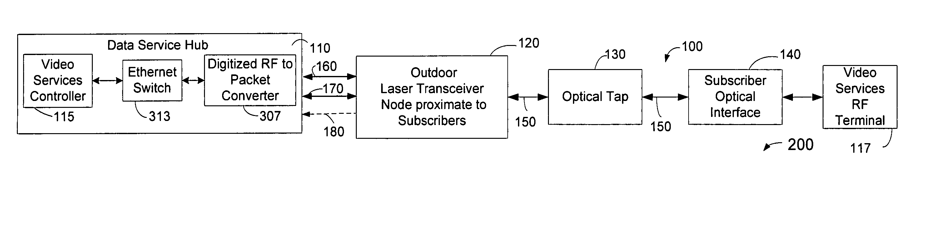
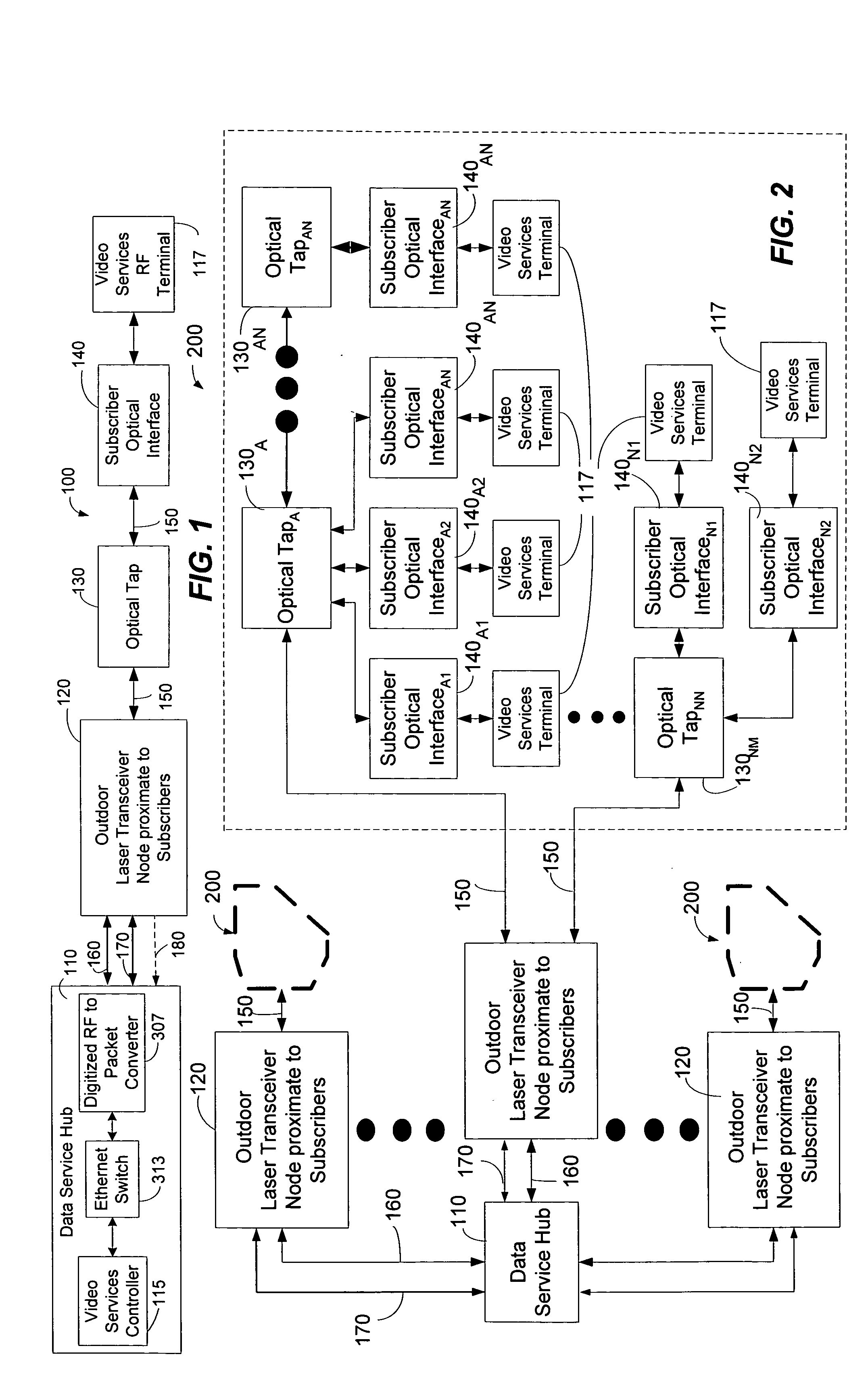
[0057] The present invention may be embodied in hardware or software or a combination thereof disposed within an optical network. In one exemplary embodiment, the present invention provides a method for inserting RF packets between upstream packets comprising data generated by a subscriber with a communication device such as a computer or internet telephone. In this way, the present invention can provide an RF return path for legacy video service terminals that shares a return path for regular data packets in an optical network architecture. Video service terminals (VSTs) can comprise set top terminals or other like communication devices that may employ RF carriers to transmit upstream information.

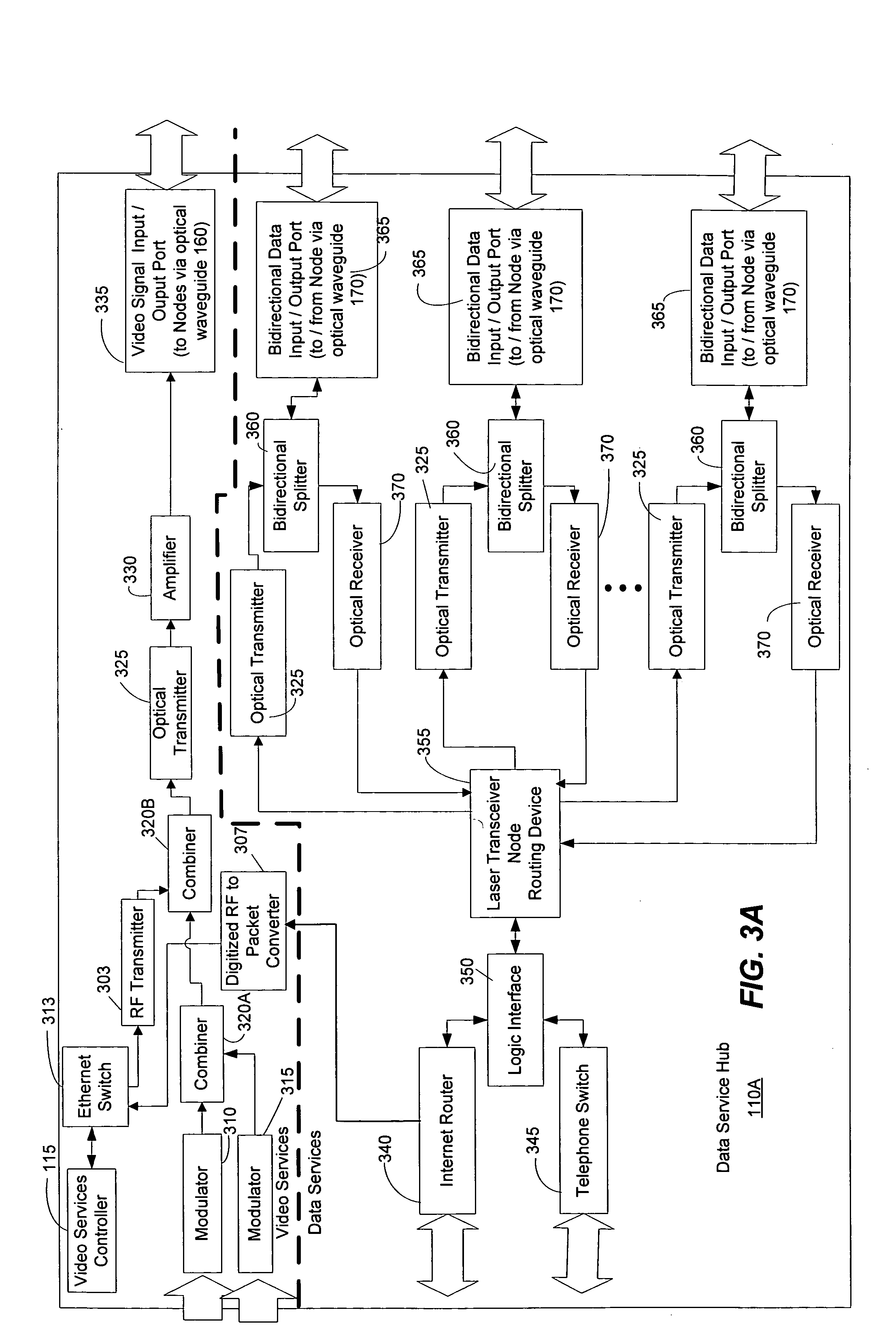
[0058] According to one exemplary embodiment, a data service hub or what is usually referred to as a head-end in industry, may comprise a digitized-RF-to-packet-converter (DRPC) that demodulates received upstream, return RF packets into standard packets such as Ethernet packets. These Eth...


PUM


Abstract

A return path system includes inserting RF packets between regular upstream data packets, where the data packets are generated by communication devices such as a computer or internet telephone. The RF packets can be derived from analog RF signals that are produced by legacy video service terminals. At a data service hub, a digitized-RF-to-packet converter (DRPC) can convert the RF packets into standard sized packets such as Ethernet packets for processing by a video services controller. In this way, the present invention can provide an RF return path for legacy terminals that shares a return path for regular data packets in an optical network architecture.

Description

STATEMENT REGARDING RELATED APPLICATIONS [0001] The present application is a continuation-in-part of non-provisional patent application entitled, “System and Method for Communicating Optical Signals Between A Data Service Provider and Subscribers,” filed on Jul. 5, 2001 and assigned U.S. application Ser. No. 09 / 899,410; and the present application claims priority to provisional patent application entitled, “METHOD AND SYSTEM FOR PROVIDING A RETURN PATH FOR SIGNALS GENERATED BY LEGACY TERMINALS IN AN OPTICAL NETWORK-3,” filed on Dec. 5, 2003 and assigned U.S. Application Ser. No. 60 / 527,867.TECHNICAL FIELD [0002] The present invention relates to video, voice, and data communications. More particularly, the present invention relates to a fiber-to-the-home (FTTH) system that is capable of propagating RF terminal signals from a subscriber to a data service provider. BACKGROUND OF THE INVENTION [0003] The increasing reliance on communication networks to transmit more complex data, such a...

Claims


Application Information

Patent Timeline
IPC IPC(8): H04B10/272H04J14/02H04N7/173H04N7/22H04Q11/00
CPCH04J14/0226H04J14/0252H04J14/0282H04J14/0286H04J14/0298H04N7/17309H04N7/22H04N21/4402H04N21/6168H04Q11/0067H04Q11/0071H04J14/0232H04J14/0238H04J14/0247H04J14/028
Inventor FARMER, JAMES O.THOMAS, STEPHEN A.QUINN, PATRICK W.ANTHONY, DEVEN J.
Owner ARRIS SOLUTIONS
Why Eureka
Try Eureka