Oil return control in refrigerant system

Inactive Publication Date: 2005-06-16
CARRIER CORP
View PDF6 Cites 20 Cited by
  • Summary
  • Abstract
  • Description
  • Claims
  • Application Information

AI Technical Summary

Benefits of technology

[0010] The subject of yet another embodiment is oil pump out due to excessive superheat entering the compressor. This problem is most prominent in long lines leading from an evaporator exit to a compressor suction (vapor gains superheat between evaporator exit and compressor entrance). For this case, especially if coupled with low mass flow operation, the oil will be logged in this section of the pipe, as its viscosity increases rapidly as superheat i

Problems solved by technology

However, with the two circuits running, the amount of cold air delivered is often too high for the demand.
This leads to oil pump out as the oil is pumped out on the start up, but does not have sufficient time to return back to the compressor before the units start off again.
In this case, the oil pump out can occur because the refrigerant

Method used


Image

  • Oil return control in refrigerant system
  • Oil return control in refrigerant system

Examples


Embodiment Construction

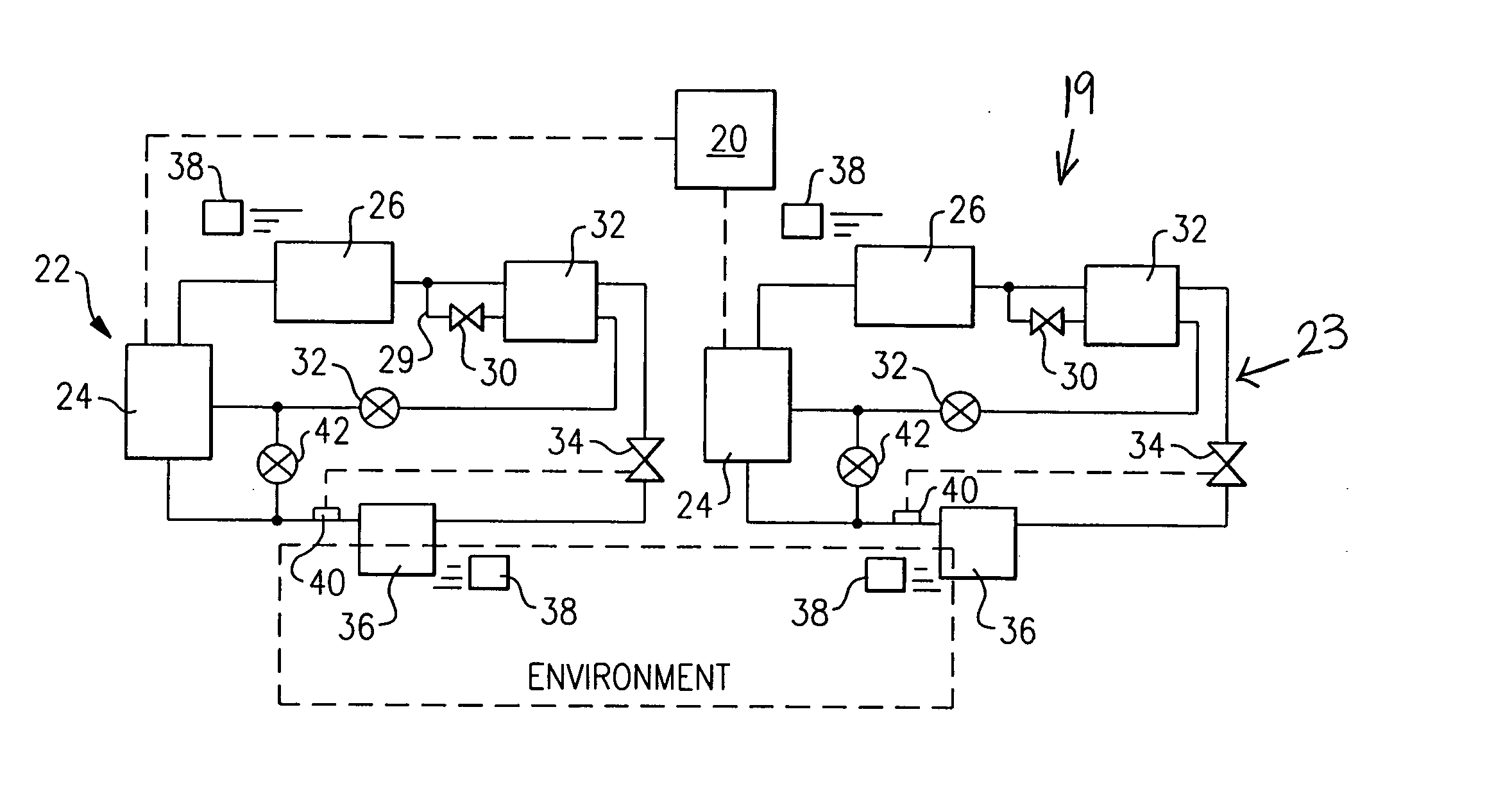
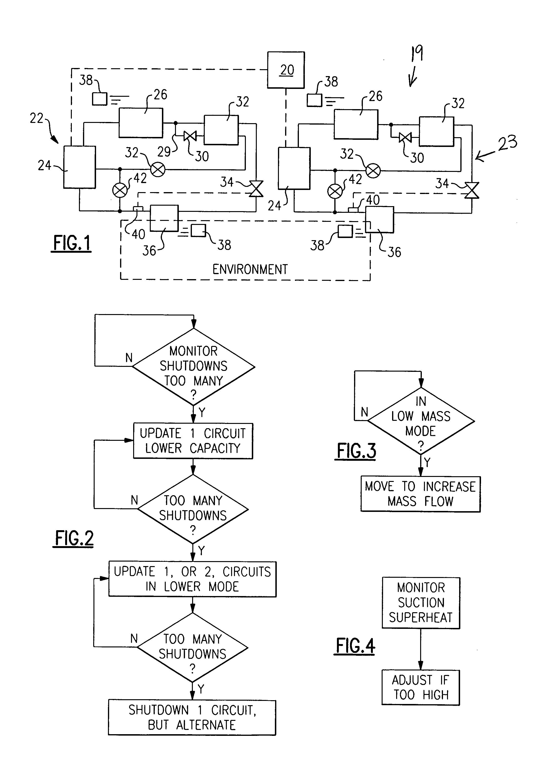
[0016] A refrigerant circuit 19 is illustrated schematically in FIG. 1 having a control unit 20 controlling a pair of separate circuits 22 and 23. Some aspects of this invention are particularly directed to such a multi-circuit system (in particularly the algorithm of FIG. 2). However, the FIG. 3 and FIG. 4 algorithm aspects may extend to refrigerant cycles having only a single circuit. While a two circuit system is shown, additional circuits may be used.

[0017] As shown in FIG. 1, each circuit 22 and 23 includes a compressor 24 delivering refrigerant to a condenser 26, which in turn delivers refrigerant to an economizer heat exchanger 28. A tap line 29 taps refrigerant from the line downstream of the condenser 26 through an economizer expansion device 30. While the flow through the tap 29 and the main flow from the condenser to the economizer heat exchanger 28 are shown moving in the same direction, most preferably, they are in a counter-flow relationship. However, for ease of illu...


PUM


Abstract

Several control algorithms reduce the likelihood of insufficient oil return to the compressor. One algorithm is useful in a multi-circuit refrigerant system. A control reduces the cooling capacity of one of the circuits if the number of compressor start/stop cycles becomes excessive. By reducing the capacity, the control will reduce the number of compressor start/stop cycles for a circuit. In this manner, the oil continues to circulate through the circuit, and is more efficiently returned to the compressor. Another problem area associated with a poor oil return back to the compressor is when there is low mass flow rate of refrigerant circulating through the system. Various ways of increasing the refrigerant mass flow rate are disclosed to ensure proper oil return to the compressor. Also, if oil return problems are likely due to an undesirably high oil viscosity at the vapor portion of the evaporator or suction line, then steps are taken to reduce oil viscosity. Overall, the present invention discloses three distinct algorithms that may be utilized, either separately or in combination, to ensure better flow of oil back to the compressor. The invention enhances system and compressor reliability and performance as well as prevents the compressor damage.

Description

BACKGROUND OF THE INVENTION [0001] This invention relates to several methods of ensuring oil return from the various system components to the compressor under various operational conditions, and preventing oil pump out from the compressor causing subsequent compressor damage. [0002] Refrigerant cycles are utilized to provide cooling or heating. A refrigerant is compressed by a compressor, and then moved through a series of heat exchangers, connection lines and expansion devices. [0003] There are many distinct configurations and arrangements of refrigerant cycles. One of the options is the use of multi-circuit refrigerant systems. A multi-circuit system has at least two circuits, each including a compressor and the associated heat exchangers, connection lines and expansion devices for conditioning a common area. The circuits, each including a compressor, condenser, expansion device, and evaporator are controlled to maintain a desired temperature in an environment to be cooled or heat...

Claims


Application Information

Patent Timeline
IPC IPC(8): F25B49/02
CPCF25B49/02F25B2400/06F25B2600/0261F25B2500/16F25B2400/13F25B2500/15
Inventor LIFSON, ALEXANDERTARAS, MICHAEL F.DOBMEIER, THOMAS J.
Owner CARRIER CORP
Why Eureka
Try Eureka