Fuel tank assembly and method of assembly

a technology of fuel tanks and tanks, applied in the directions of transportation and packaging, transportation items, other domestic objects, etc., can solve the problems of prolonged manufacturing cycle times, problems such as problems still arising, and vapor may permeate the walls of fuel tanks

Inactive Publication Date: 2005-06-16
AUTOMOTIVE COMPONENTS HOLDINGS
View PDF21 Cites 33 Cited by
  • Summary
  • Abstract
  • Description
  • Claims
  • Application Information

AI Technical Summary

Problems solved by technology

One problem with thermoplastic fuel tanks is that vapors may permeate through the fuel tanks walls.
While permeation resistant layers and blow molded fuel tanks reduce permeation, problems still arise when components, such as fill tubes, vent tubes, roll over valves, and vent valves, are attached to the fuel tank.
However, each opening breaches the permeation resistant layer creating permeation pathways.
Attempts to offset the component from the limited bonding area have resulted in prolonged manufacturing cycle times due to the delay in cooling the heating elements used to weld the component to the tank wall before removal from the fuel tank.
Further, commonly used heating elements (such as hot plates) have significant mass requiring excessive time to heat and cool the heating element.

Method used


Image

  • Fuel tank assembly and method of assembly
  • Fuel tank assembly and method of assembly
  • Fuel tank assembly and method of assembly

Examples


Embodiment Construction

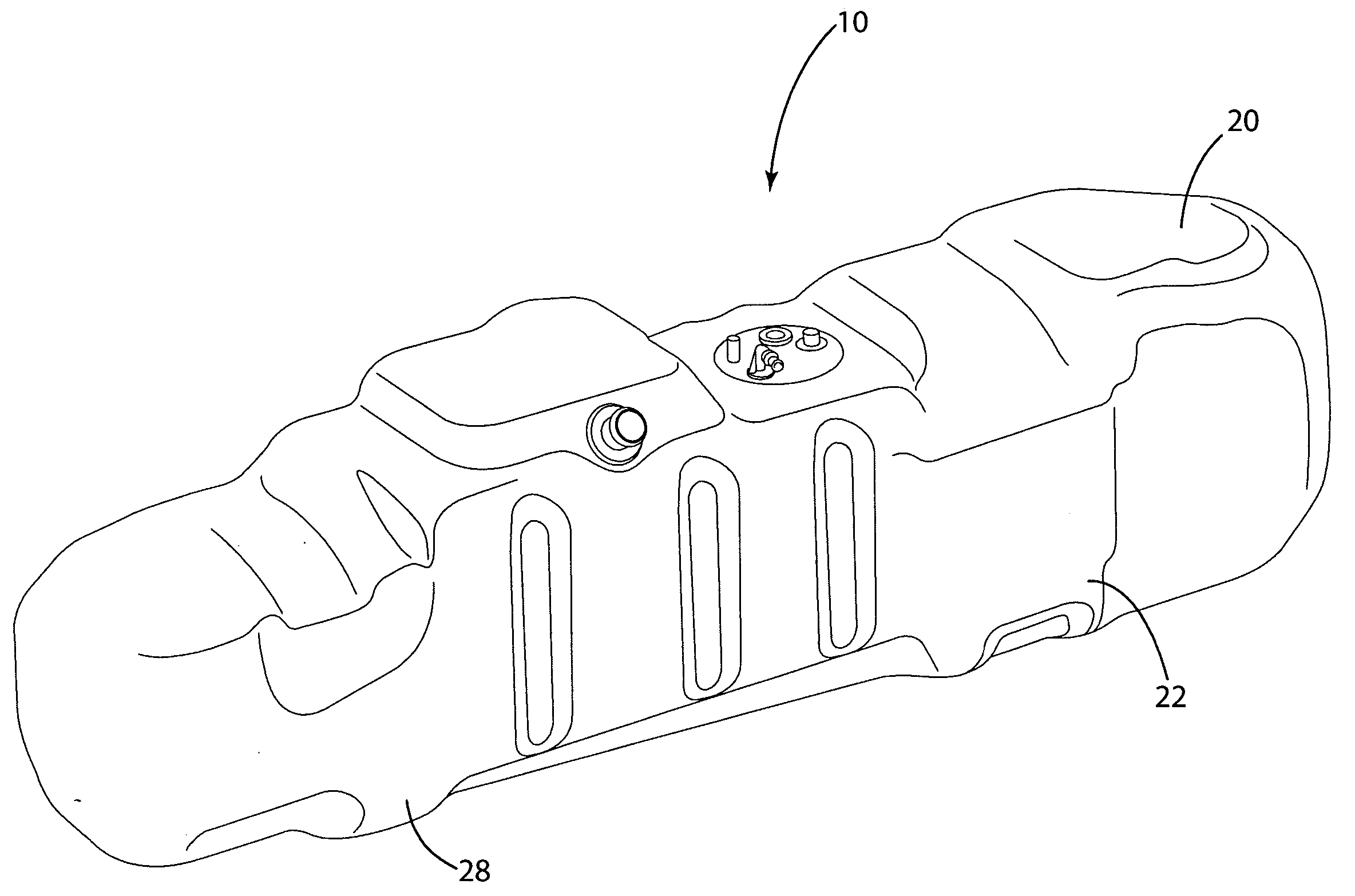
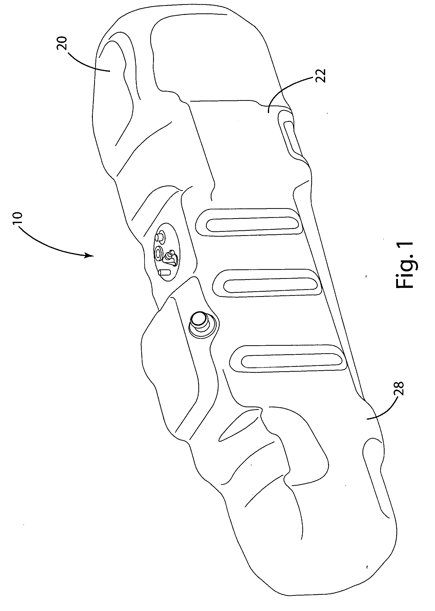
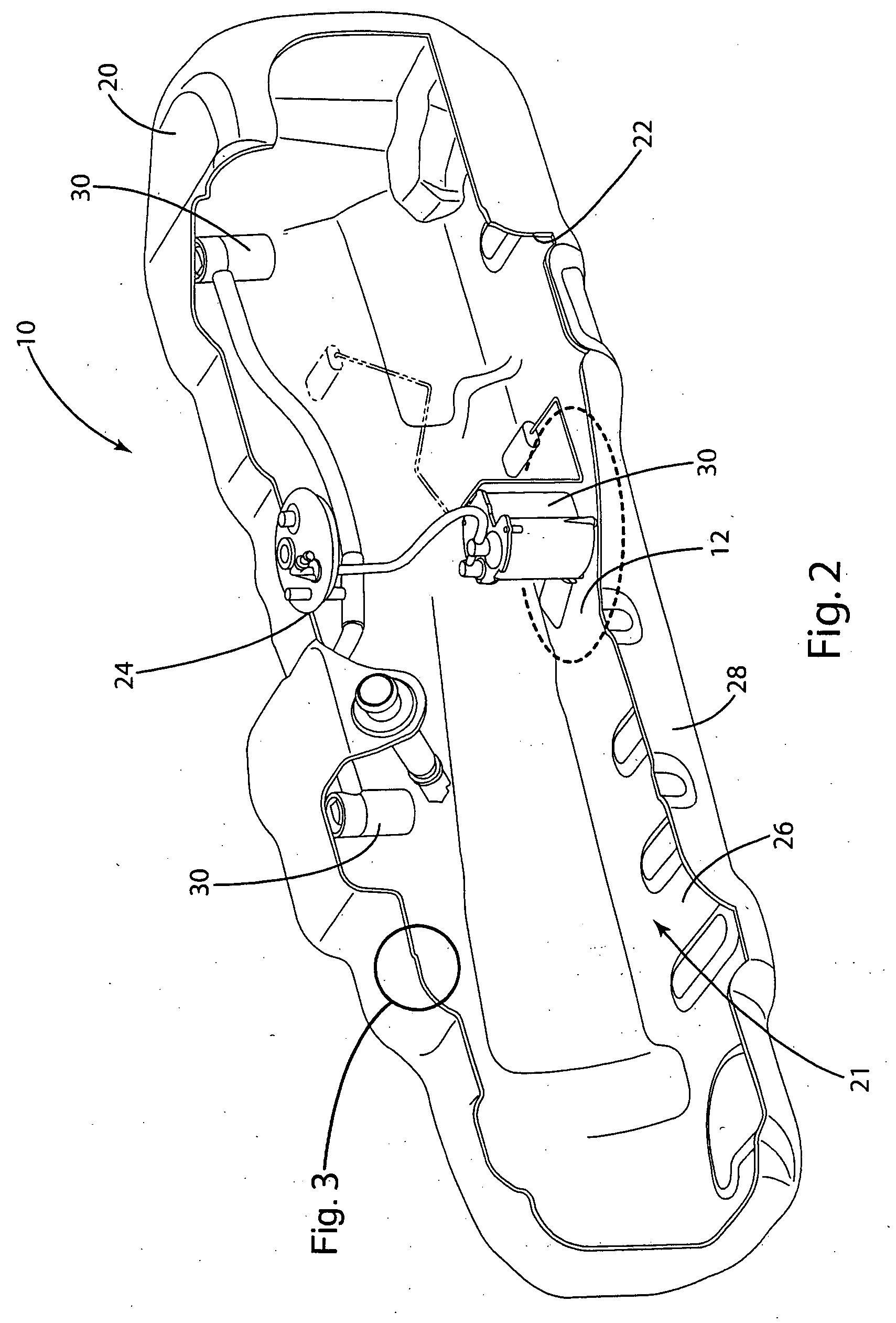
[0016] A fuel tank assembly 10 constructed in accordance with the illustrated embodiment is shown in FIGS. 1 and 2. The fuel tank assembly 10 generally includes a fuel tank 20 defining an access opening 24 and having an inner surface 26 to which a component 30 is induction welded. Induction welding the component 30 to the fuel tank 20 allows the component to be displaced from the opening 24 without encountering many of the problems typically associated with using a heating element to directly weld the component. Of particular note is that the ability to place the component 30 where desired in the fuel tank, including in areas offset from the access opening 24 provides additional mounting locations, eliminates many packaging concerns and may improve performance of certain components. Induction welding also decreases cycle times by reducing the wait time associated with heating and cooling of conventional heating elements.

[0017] A variety of induction welding assemblies may be used t...


PUM

PropertyMeasurementUnit
heataaaaaaaaaa
permeationaaaaaaaaaa
permeation resistantaaaaaaaaaa

Abstract

The present invention relates to a fuel tank assembly and method of securing a component in a fuel tank using induction welding. The method generally includes the steps of placing a component in contact with an inner surface of a fuel tank and inductively welding the component to the inner surface of the fuel tank. The fuel tank assembly generally includes a fuel tank having a wall having a cavity, an inner surface, an outer surface, and an access opening extending through the wall and communicating with the cavity and a component inductively welded to said inner surface.

Description

BACKGROUND OF THE INVENTION [0001] The present invention relates to a fuel tank assembly and method of securing a component in a fuel tank using induction welding. [0002] To save time and money and improve reliability, manufacturers have been switching from metal fuel tanks to thermoplastic fuel tanks. Thermoplastic fuel tanks generally have lower material cost, lower manufacturing costs, increased longevity, and are not subject to corrosion. One problem with thermoplastic fuel tanks is that vapors may permeate through the fuel tanks walls. To address this permeation problem and in view of stricter emissions requirements, manufacturers have added permeation resistant layers to fuel tanks and have attempted to form fuel tanks out of as few pieces as possible. [0003] While permeation resistant layers and blow molded fuel tanks reduce permeation, problems still arise when components, such as fill tubes, vent tubes, roll over valves, and vent valves, are attached to the fuel tank. Durin...

Claims


Application Information

Patent Timeline
Patent Type & Authority Applications(United States)
IPC IPC(8): B29C65/00B29C65/02B29C65/36B60K15/03B60P3/00
CPCB29C66/61B29L2031/7172B60K15/03177B29C66/53245B29C65/3612B29C65/362B29C65/3676B60K2015/03453B29C66/8324B29C66/863B29C66/71B29C66/112B29C66/131B29C65/7847B29C66/7234B29C66/8161B29K2023/00B29K2023/086B29K2077/00
Inventor VORENKAMP, ERICH J.SCHULTE, KALE S.KNAGGS, RICHARD A.SEKELA, RYAN F.HARRIS, MARK A.
Owner AUTOMOTIVE COMPONENTS HOLDINGS
Why Eureka
Try Eureka