In-Mould labelling

Inactive Publication Date: 2005-06-16
NOKIA CORP
View PDF14 Cites 26 Cited by
  • Summary
  • Abstract
  • Description
  • Claims
  • Application Information

AI Technical Summary

Problems solved by technology

There are various problems associated with the FIML process.
One problem is how to accurately locate the fabric label within the injection moulding tool without marking or damaging the fabric.
Another prob

Method used


Image

  • In-Mould labelling
  • In-Mould labelling
  • In-Mould labelling

Examples


Embodiment Construction

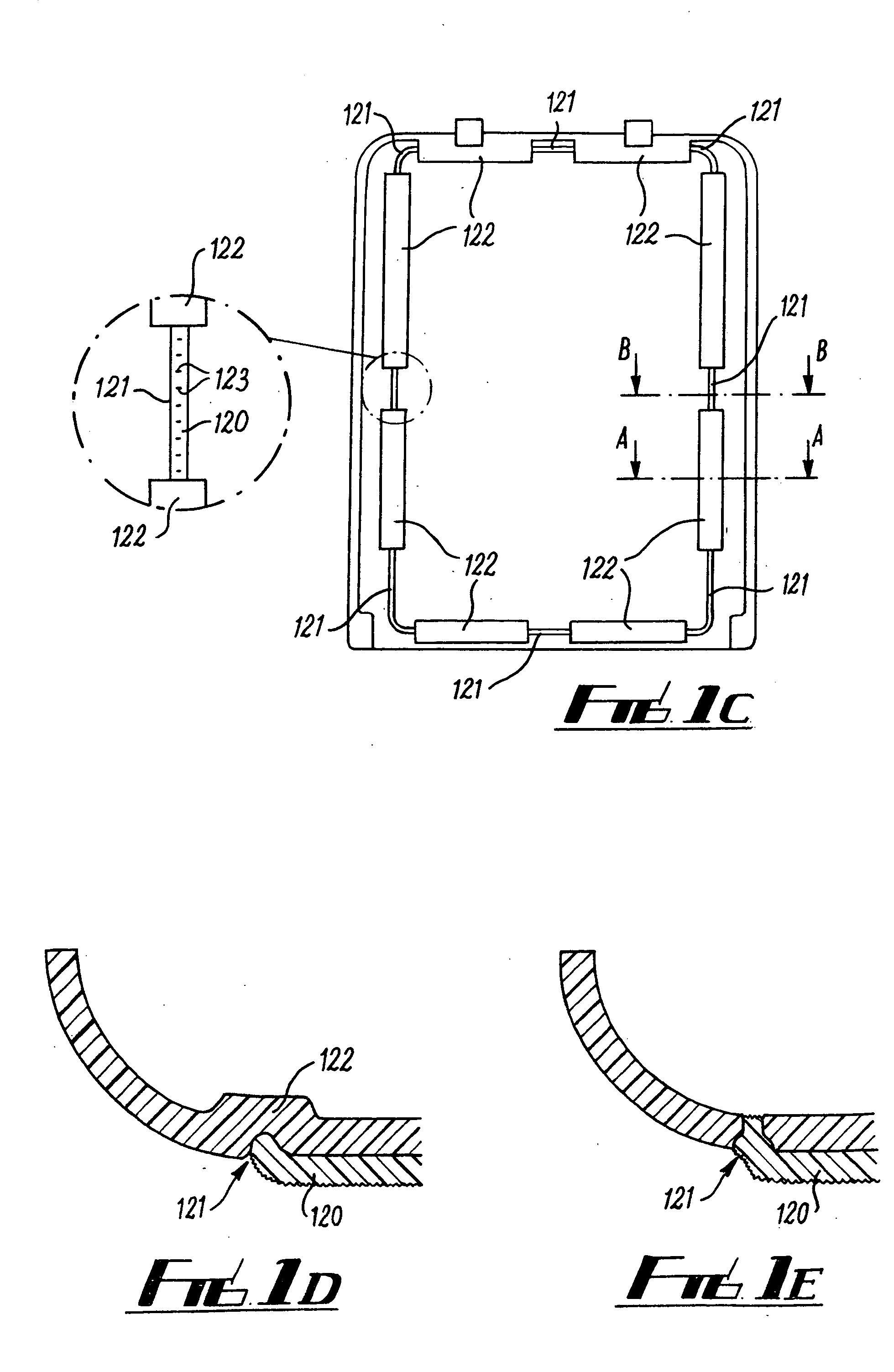
[0033] Embodiments of the invention use the Fabric In-Mould Label process. In this process, fabric is laminated to a film, which may be a polymer film. The laminate may be thermo-formed into a 3D shape. A label is then cut from the laminate and placed into an injection moulding tool. The label may be two-dimensional or, if the laminate was formed, a three-dimensional pre-form. Material such as plastics or polymer is injected into the mould and adheres to the film portion of the laminate pre-form. The result, an In-Mould Label (IML), is a moulded article with the fabric surface of the label pre-form over at least part of one or more surfaces.

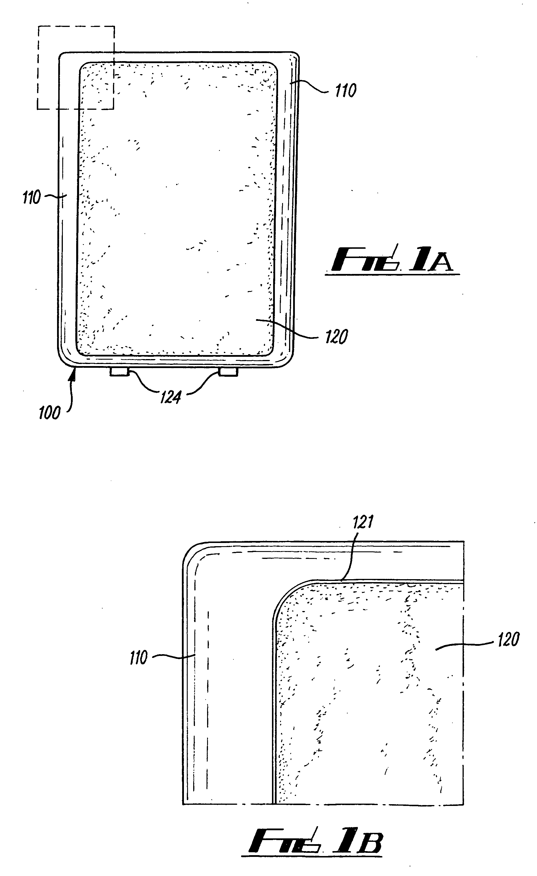
[0034]FIG. 1A illustrates a battery cover for an electronic device such as a radio telephone formed using the FIML process. The battery cover 100 is a FIML comprising polymer 110 and a fabric laminate 120. The fabric laminate 120 may, for example, be 0.8 millimetre thick Alcantara bonded to 0.2 millimetre polycarbonate / ABS film using a polyureth...


PUM

PropertyMeasurementUnit
Thicknessaaaaaaaaaa
Thicknessaaaaaaaaaa
Volumeaaaaaaaaaa

Abstract

An In-Mould Labelling process comprising: clamping a label within a mould void of an injection moulding tool; and injecting material into the mould void while the label is clamped. An In-Mould Labelling process comprising: placing a label between a first mould void and a second, separate mould void; and injecting material into the first and second mould voids.

Description

BACKGROUND TO THE INVENTION [0001] Embodiments of the present invention relate to In-Mould Labelling. In particular, embodiments relate to Fabric In-Mould Labelling. [0002] Users of radio telephones and other portable devices may want to change the appearance of their device by replacing its housing or cover with another of a different appearance. Such replaceable covers include in-mould decorated covers. [0003] The in-mould labelling (IML) process typically involves the following steps. First, the desired pattern is printed on a film, then, the printed film is thermo- formed into the desired three-dimensional shape i.e. the cover or housing of a radio telephone. Next, a pre-form is cut from the shaped film and is placed in a mould tool and held in place using vacuum suckers. Then polymer is injected into the mould cavity and bonded with the pre-form. The result is a decorated moulded article. [0004] It would be desirable to provide a greater variety of coverings for articles. It wo...

Claims


Application Information

Patent Timeline
IPC IPC(8): B29C45/00B29C45/14B29C45/36B29C70/68B29C70/78G01S1/00G01S5/00H04Q7/32H04Q7/38
CPCB29C45/0081B29C45/14065B29L2031/3431B29C2045/14098B29C2045/14918B29C45/1418B29C45/14B29C45/14008B29C45/14262B29C45/36B29C70/68B29C70/78B32B27/10
Inventor WILSON, SIMONRUCK, SHAUN
Owner NOKIA CORP
Why Eureka
Try Eureka