Cannulated injection system

a cannulated injection and cannula technology, applied in the field of cannulated injection systems, can solve the problems of difficult material placement, affecting the choice of injection device and the manner, and difficulty in removing trapped air

Inactive Publication Date: 2006-11-09
PAULOS LONNIE +1
View PDF0 Cites 22 Cited by
  • Summary
  • Abstract
  • Description
  • Claims
  • Application Information

AI Technical Summary

Benefits of technology

[0020] In an alternate embodiment for use with low-viscosity materials only, the piston assembly does not contain a means for aspirating trapped air therethrough since trapped air can be expelled by pointing the nozzle upward and advancing the piston into the body. The cannulated piston assembly does, however, contain a sealing means for preventing material loss around the guide wire and through the cannulation during use.
[0021] Some injectable, healing enhancing products are supplied as two components which are mixed immediately prior to use, the ratio of the mix being specified by the manufacturer

Problems solved by technology

The sites at which the healing enhancing products must be placed are frequently difficult to access making the required accurate placement of the materials difficult.
The viscosity of the materials to be injected also a

Method used


Image

  • Cannulated injection system
  • Cannulated injection system
  • Cannulated injection system

Examples


Embodiment Construction

[0086] Referring Now to the Drawings

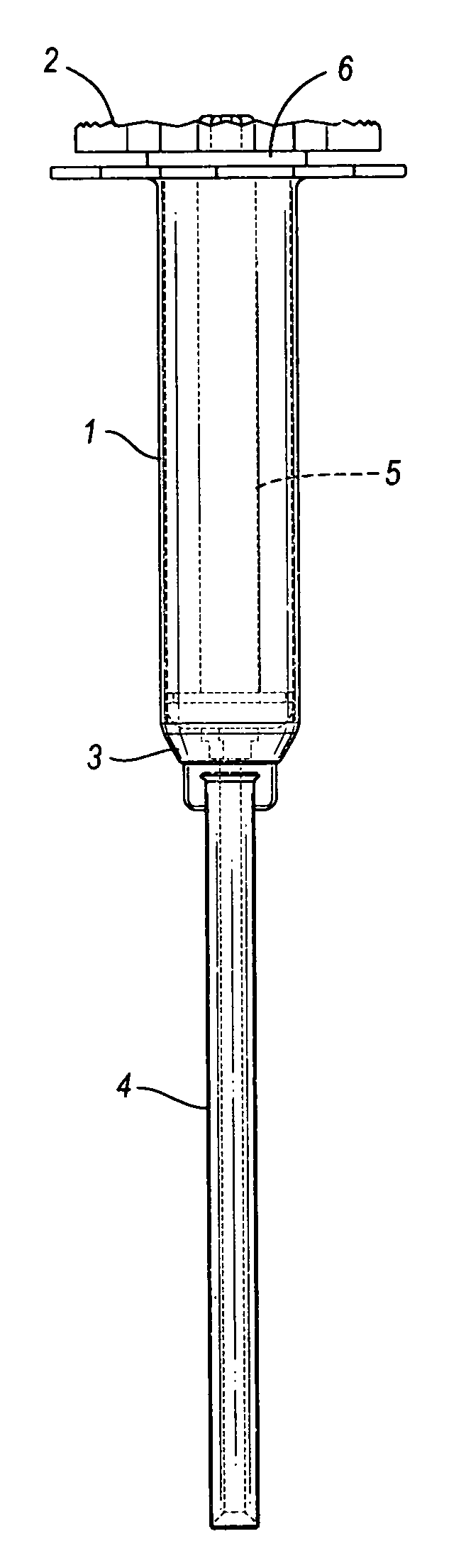
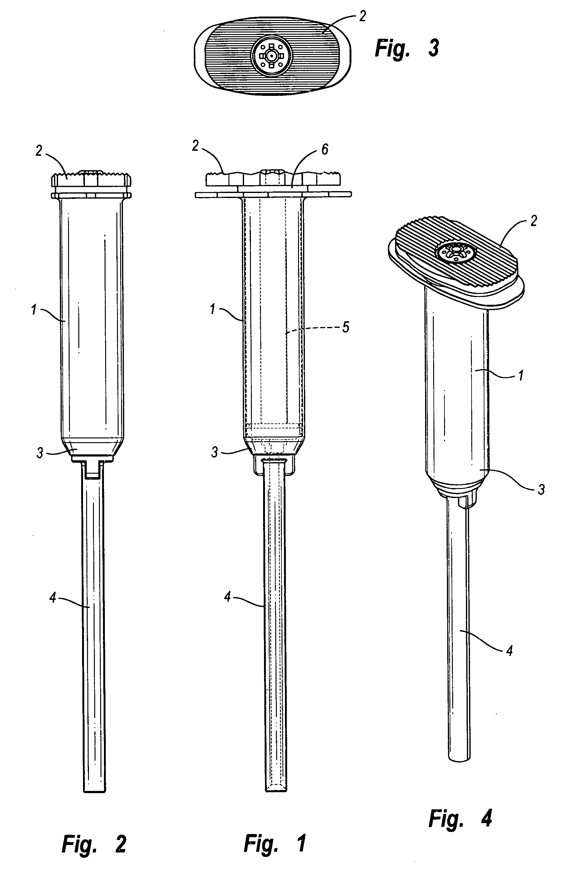
[0087] In the portion of the invention shown in FIGS. 1 through 4, cannulated injection system 1 has a proximal end 2 and a distal end 3 to which is mounted nozzle 4. System 1 has a hollow body 5 and a piston assembly 6 in the body.

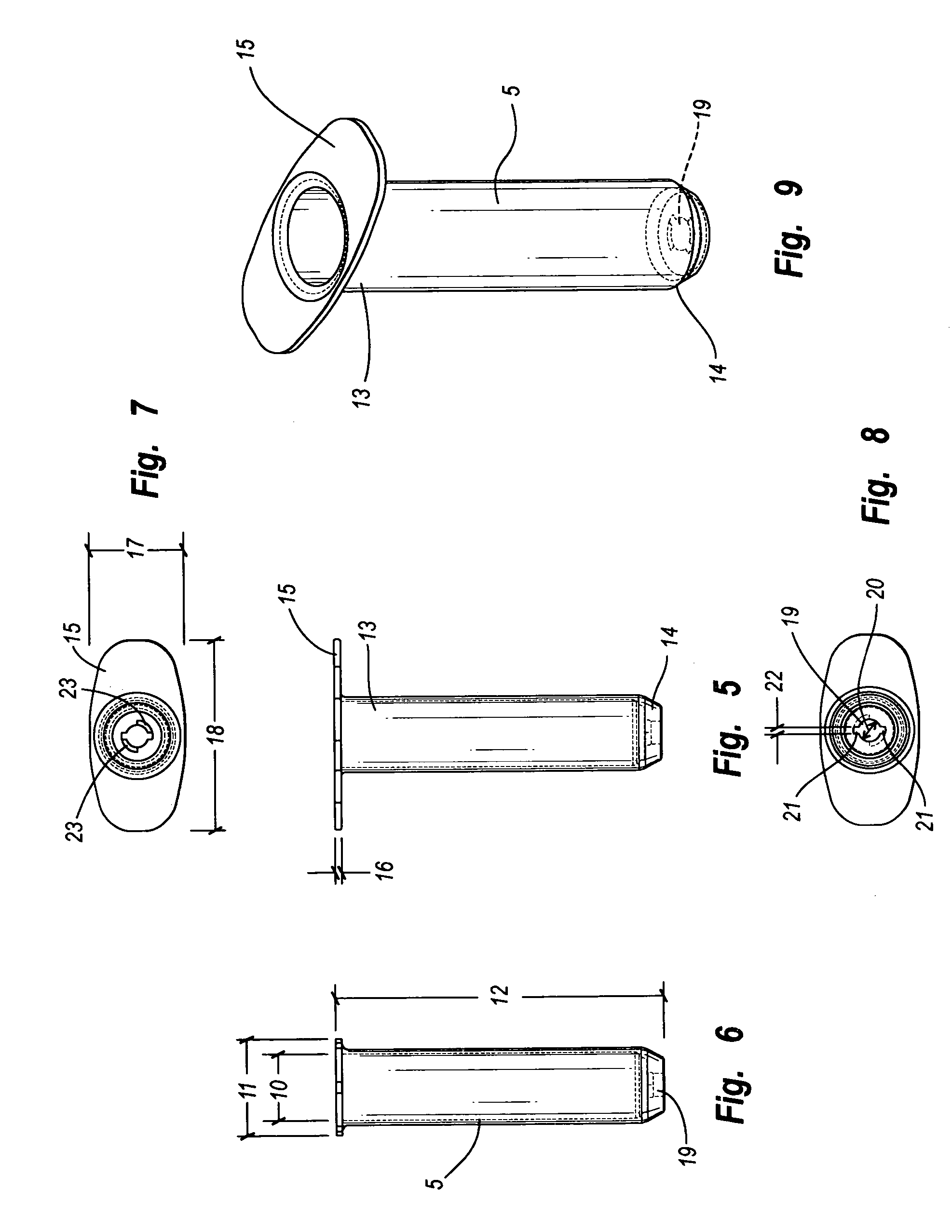
[0088] Referring to FIGS. 5-9, body 5 of inner diameter 10, outer diameter 11 and length 12 has a proximal end 13 and a distal end 14. Proximal end 13 has a flange 15 of thickness 16 and, as viewed in FIG. 7, an approximately rectangular shape of width 17 and length 18. Distal end 14 has a cannulation 19 of diameter 20, grooves 21 of width 22 and shoulders 23.

[0089] Referring to FIGS. 10-14, piston outer member 30 has a proximal end 31 having a flange 32 of thickness 33 and approximate rectangular shape of width 34 and length 35. Protruding from the most proximal surface 36 of flange 32 is cylindrical projection 37 of diameter 38 and height 52, displaced a distance 39 from axis 40 of outer member 30 and at angle 41. ...


PUM


Abstract

A cannulated injection system having or more hollow bodies to receive material to be injected, a piston in each said hollow body to force material from said body through a nozzle having a passageway sized and selected to accommodate flow of the material therethrough and with the passageway arranged to accommodate a guide wire passed therethrough, the guide wire further being passed through support structure including a piston and hollow body in which said piston reciprocates or a support structure for a plurality of hollow bodies in which pistons reciprocates during use in simultaneously injecting material from said hollow bodies through said injection tip and around a guide wire passing through the tip.

Description

CROSS-REFERENCE TO RELATED APPLICATIONS [0001] Not Applicable. STATEMENT REGARDING FEDERALLY SPONSORED RESEARCH OR DEVELOPMENT [0002] Not Applicable. REFERENCE TO MICROFICHE APPENDIX [0003] Not Applicable. BACKGROUND OF THE INVENTION [0004] 1. Field of the Invention [0005] This invention relates to injection systems and more particularly, to a cannulated injection system for orthopedic applications which may be guided to its desired location by a previously placed guide wire. [0006] 2. Description of the Prior Art [0007] Recently a number of healing enhancing products have come to market. These include calcium triphosphates, high hyaluronic acid products, platelet healing factors and others. These materials are used to enhance bone tunnel fixation of soft tissue ligament grafts as well as arthroscopically treating non-unions of long bones, bone cysts of the hip, knee and other related skeletal abnormalities. The sites at which the healing enhancing products must be placed are freque...

Claims


Application Information

Patent Timeline
IPC IPC(8): A61M5/00
CPCA61B17/3472A61B17/8822A61B17/8827A61F2/4601A61M5/19A61B2017/8838
Inventor PAULOS, LONNIEVAN WYK, ROBERT
Owner PAULOS LONNIE
Why Eureka
Try Eureka