
Heterocyclic compound and organic electroluminescent device comprising the same

a technology of organic electroluminescent devices and compound compounds, which is applied in the direction of discharge tubes/lamp details, organic chemistry, discharge tubes luminescnet screens, etc., can solve the problems that the life, efficiency and power consumption of conventional electroluminescent devices employing hole injection layers and/or hole transport layers still needs to be improved, so as to achieve high charge transporting capability, high glass transition temperature, and high electrical stability

Inactive Publication Date: 2010-02-11
SAMSUNG DISPLAY CO LTD
View PDF5 Cites 22 Cited by
  • Summary
  • Abstract
  • Description
  • Claims
  • Application Information

AI Technical Summary

Benefits of technology

[0007]The present embodiments provide a heterocyclic compound having a high electrical stability, a high charge transporting capability, a high glass transition temperature, and a crystallization preventing capability, which is used as an organic layer forming material that is suitable for use in all-color fluorescent and phosphorescent organic light emitting devices such as red, green, blue, and white fluorescent and phosphorescent organic light emitting devices.
[0008]The present embodiments also provide an organic electroluminescent device including an organic layer comprising the heterocyclic compound, thereby having high efficiency, a low driving voltage, and high luminosity, and a flat panel display device including the organic electroluminescent device.

Problems solved by technology

However, organic electroluminescent devices employing conventional hole injection layer and / or hole transport layer forming materials still needs to be improved in terms of lifetime, efficiency, and power consumption.

Method used


Image

  • Heterocyclic compound and organic electroluminescent device comprising the same
  • Heterocyclic compound and organic electroluminescent device comprising the same
  • Heterocyclic compound and organic electroluminescent device comprising the same

Examples


synthesis example 1

Preparation of Compound 1

[0069]Compound 1 was synthesized through a reaction pathway illustrated in Reaction Scheme 1 below.

[0070][31.2 g of dibromo biphenyl (0.10 mole) and 43.2 g of benzophenone hydrazone (0.22 mole) were dissolved in 400 ml of toluene. Then, 1.12 g of Pd(OAc)2 (5.0 mole %), 2.6 g of phosphine ligand (5.5 mole), and 28.8 g of NaOtBu (0.30 mole) were added to the mixture and the resultant mixture was stirred while refluxing for 12 hours in a nitrogen atmosphere. After the reaction was terminated, methylene chloride was added to the reaction solution at room temperature and the resultant solution was filtered using cellite. The solution was then extracted using 50 ml of ethylether three times. The collected organic layer was dried over magnesium sulfate and a solvent was evaporated to obtain the residue. The residue was purified by silicagel column chromatography to obtain 4.21 g (yield 85%) of a white solid Intermediate A.

[0071]1H NMR (CD2Cl2, 400 MHz) δ (ppm) 7.52...

synthesis example 2

Preparation of Compound 7

[0078]Compound 7 was synthesized through a reaction pathway illustrated in Reaction Scheme 2 below.

[0079]6.58 g of 1-naphthyl-phenylamine (30.0 mmole) and 12.7 g of 4-bromoiodobenzene (45.0 mmole) were dissolved in 150 ml of toluene. Then, 550 mg of Pd2dba3 (2.0 mole %), 300 mg of phosphine ligand (2.0 mole %), and 4.32 g of NaOtBu (45.0 mole) were added to the mixture and the resultant mixture was stirred while refluxing for 4 hours in a nitrogen atmosphere. After the reaction was terminated, water was added to the reaction solution at room temperature and the resultant solution was extracted using 200 ml of methylene chloride twice. The collected organic layer was dried over magnesium sulfate and a solvent was evaporated to obtain the residue. The residue was purified by silicagel column chromatography to obtain 4.7 g (yield 42%) of a light yellow solid Irtermediate C.

[0080]1H NMR (CD2Cl2, 400 MHz) δ (ppm) 7.63 (d, 2H), 7.01-7.30 (m, 8H), 6.35-6.62 (m, 6H)...

synthesis example 3

Preparation of Compound 9

[0084]Compound 9 was synthesized through a reaction pathway illustrated in Reaction Scheme 3 below.

[0085]Intermediate D (yield 45%) was synthesized using the method similar to that used in the synthesis of Intermediate C.

[0086]1H NMR (CD2Cl2, 400 MHz) δ (ppm) 7.51-7.44 (m, 2H), 7.01-7.23 (m, 8H), 6.35-6.76 (m, 6H); 13C NMR (CD2CL2, 100 MHz) δ (ppm) 142.6, 141.6, 140.4, 133.5, 132.7, 129.4, 127.8, 126.6, 126.4, 125.0, 124.5, 123.7, 122.9, 121.5, 121.1, 117.5, 117.0, 107.4.

[0087](2) Synthesis of Compound 9

[0088]Compound 9 (yield 73%) was synthesized using the same method as that used in the synthesis of Compound 1, except that Intermediate D was used instead of 4-bromophenyl-diphenyl amine.

[0089]1H NMR (CD2Cl2, 400 MHz) δ (ppm) 7.76-7.80 (m, 6H), 7.65 (d, 2H), 7.54 (d, 2H), 7.20-7.46 (m, 28H), 7.10 (t, 2H), 2.37 (s, 6H), 2.29 (s, 6H); 13C NMR (CD2Cl2, 100 MHz) δ (ppm) 147.5, 146.8, 145.1, 136.4, 134.7, 134.4, 133.4, 132.5, 130.3, 129.4, 129.2, 129.1, 128.6, 12...


PUM

PropertyMeasurementUnit
Electric chargeaaaaaaaaaa
Efficiencyaaaaaaaaaa
Fluorescenceaaaaaaaaaa

Abstract

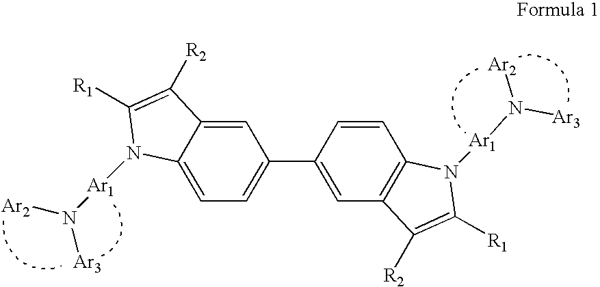
Provided are a heterocyclic compound represented by Formula 1 below and an organic electroluminescent device including an organic layer comprising the heterocyclic compound:wherein Ar1, Ar2, Ar3, R1, and R2 are the same as defined in the detailed description. The heterocyclic compound represented by Formula 1 has excellent electrical characteristics and an excellent charge transporting capability, and thus the heterocyclic compound of Formula 1 can be used as a hole injecting material, a hole transporting material, and / or a light emitting material that are suitable for all-color fluorescent and phosphorescent organic light emitting devices such as red, green, blue, and white fluorescent and phosphorescent organic light emitting devices. In addition, the organic electroluminescent device including an organic layer comprising the heterocyclic compound represented by Formula 1 can have a high efficiency, a low driving voltage, and high luminosity.

Description

CROSS-REFERENCE TO RELATED PATENT APPLICATION[0001]This application claims the benefit of Korean Patent Application No. 10-2008-0077548, filed on Aug. 7, 2008, in the Korean Intellectual Property Office, the disclosure of which is incorporated herein in its entirety by reference.BACKGROUND[0002]1. Field[0003]The present embodiments relate to a heterocyclic compound and an organic electroluminescent device comprising the same, and more particularly, to a heterocyclic compound having a high electrical stability, a high charge transporting capability, a high glass transition temperature, and a crystallization preventing capability, and an organic electroluminescent device including an organic layer comprising the same.[0004]2. Description of the Related Art[0005]Electroluminescent devices are a self-emission type display device and have a wide viewing angle, a high contrast ratio, and a short response time. Due to such characteristics, electroluminescent devices are getting more attent...

Claims


Application Information

Patent Timeline
IPC IPC(8): H01J1/63C07D209/08
CPCC07D209/08H05B33/20C09K2211/1007C09K2211/1011C09K2211/1014C09K2211/1029H01L51/001H01L51/0059H01L51/006H01L51/0072H01L51/0081H01L51/5012H01L51/5048H01L51/5088H05B33/14C09K11/06H10K71/164H10K85/631H10K85/633H10K85/6572H10K85/324H10K50/11H10K50/14H10K50/17C07D403/08C07D209/04
Inventor HWANG, SEOK-HWANKIM, YOUNG-KOOKKWAK, YOON-HYUNYI, JEOUNG-INOH, IL-SOO
Owner SAMSUNG DISPLAY CO LTD
Learn More