Eddy current sensors

a technology of eddy current and sensor, which is applied in the direction of coils, engine fuctions, electric/magnetic devices, etc., can solve the problems of large air gap between the sensor and the tips of the blade, low resonance frequency, and high coil impedance, so as to reduce the strength of the field through which the blade tips pass, and reduce the space

Inactive Publication Date: 2005-06-16
WESTON AEROSPACE
View PDF10 Cites 74 Cited by
  • Summary
  • Abstract
  • Description
  • Claims
  • Application Information

AI Technical Summary

Benefits of technology

[0005] With the known arrangement, the pick-up coil has to be as close to the magnet as possible to minimise space and to maximums the signal picked up. As a result the magnetic field is attracted to the core of the pick-up coil so the strengt

Problems solved by technology

For gas turbine applications, the probe is mounted outside on the turbine casing, resulting in a large air gap between the sensor and the tips of the blades.
The magnetic core of the coil increases the coil inductance resulting in a

Method used


Image

  • Eddy current sensors
  • Eddy current sensors
  • Eddy current sensors

Examples


Embodiment Construction

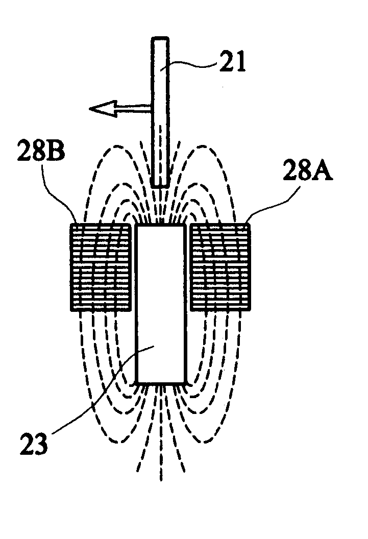
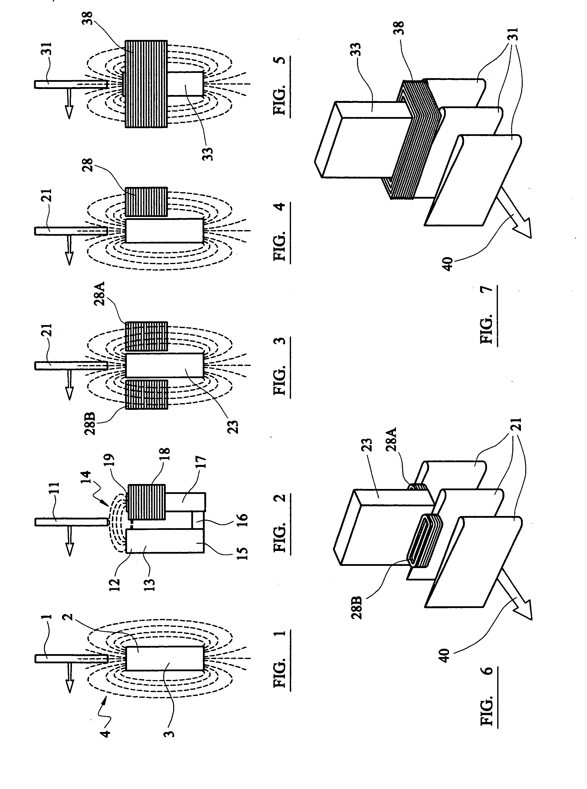
[0019]FIGS. 3 and 6 show one arrangement in accordance with the invention. Here the magnet 23 has a pick-up coil 28a adjacent it on one side and a further pick-up coil 28b on the opposite side. Both the coils 28a and 28b are formed without any core of magnetic material and have their axis parallel to the magnetic axis of the magnet. FIG. 4 shows a modification of the arrangement shown in FIG. 3, having only a single coil 28. This configuration allows space for a larger magnet, whereas the arrangement of FIG. 3 is suitable for use where the probe is to fit into a circular envelope.

[0020] As shown in FIG. 5 for some applications the coil 38 can be wound around the permanent magnet 33, thus providing a very compact construction but with a different signal output to that of FIGS. 3 and 4. Although made of magnetic material, the permanent magnet 33 cannot act as a core for the coil in the manner of a soft-iron core and so the coil acts as if it had no magnetic core.

[0021] This arrangem...


PUM


Abstract

An inductive eddy current sensor, for use for example for measuring the speed of a turbine by detecting the passage of turbine blades (21) past a probe incorporating the sensor, includes a magnet (23) positioned so that the blades (21) pass through the flux pattern generated by the magnet (23). At least one pick-up coil (28) devoid of a core of soft magnetic is positioned alongside the magnet to pick up signals generated by eddy currents generated in the turbine blades as they cut through the flux pattern, without thereby altering the flux pattern. In a modified arrangement, the pick-up coil surrounds the magnet, again without affecting the flux pattern.

Description

BACKGROUND OF THE INVENTION [0001] This invention relates to eddy current sensors for sensing the movement of an electrically conductive member along a path. Such sensors are used as speed or torque sensing probes for example for sensing the speed of the blades of the compressor or turbine of a gas turbine. Torque in a rotating member may be assessed by using two sensing probes for sensing the rotation of the member at two axially-spaced positions and determining the phase difference between the outputs of the probes. PRIOR ART [0002] An example of such a probe is disclosed in GB 2 265 221. The probe uses a strong and large magnet to form a strong magnetic field. When a metal object such as a turbine blade passes through the field, eddy currents are generated in the blade. The probe includes a pick-up coil for detecting the very small magnetic fields generated by the eddy currents induced in the tip of a moving blade. To do this task, the coil needs to have a large number of turns, ...

Claims


Application Information

Patent Timeline
IPC IPC(8): F01D17/06G01P3/49
CPCF01D17/06F05D2260/80G01P3/49
Inventor PROCTOR, KENNETH W.MAUNDER, CHRISTOPHER DAVID
Owner WESTON AEROSPACE
Why Eureka
Try Eureka