Ultrasonic locator system and method

a locator system and ultrasonic technology, applied in the field of locator systems, can solve problems such as power consumption, signal interference, reliability, etc., and plague conventional systems

Inactive Publication Date: 2005-06-16
ASCOM SWEDEN
View PDF9 Cites 17 Cited by
  • Summary
  • Abstract
  • Description
  • Claims
  • Application Information

AI Technical Summary

Problems solved by technology

However, problems with reliability, power consumption, signal interference, and the like have plagued conventional systems.
The Gaisser system has the disadvantage that it requires, in addition to the radio frequency (RF) signal, an infrared signal to accurately locate objects within the tracking environment.
Also, RF waves are very directional and in steel buildings require multiple receivers due to reflections and ghosting.
Also radio frequency signals are easily contaminated with ambient electronic noise such as motors starting, fluorescent lights, computers, and low power communication systems.
However, infrared based location systems suffer from narrow beam widths and beam blockage.
Also, infrared radiation is known to go through glass windows and, therefore, transmitters using infrared radiation can “leak” into other rooms or locations resulting in false locations.
Despite the various methods used above for tracking or locating objects within an environment, each of the above systems suffer from disadvantages such as for example, an excessive size, short battery life, interference, mislocation, and / or false location reads.

Method used


Image

  • Ultrasonic locator system and method
  • Ultrasonic locator system and method
  • Ultrasonic locator system and method

Examples


Embodiment Construction

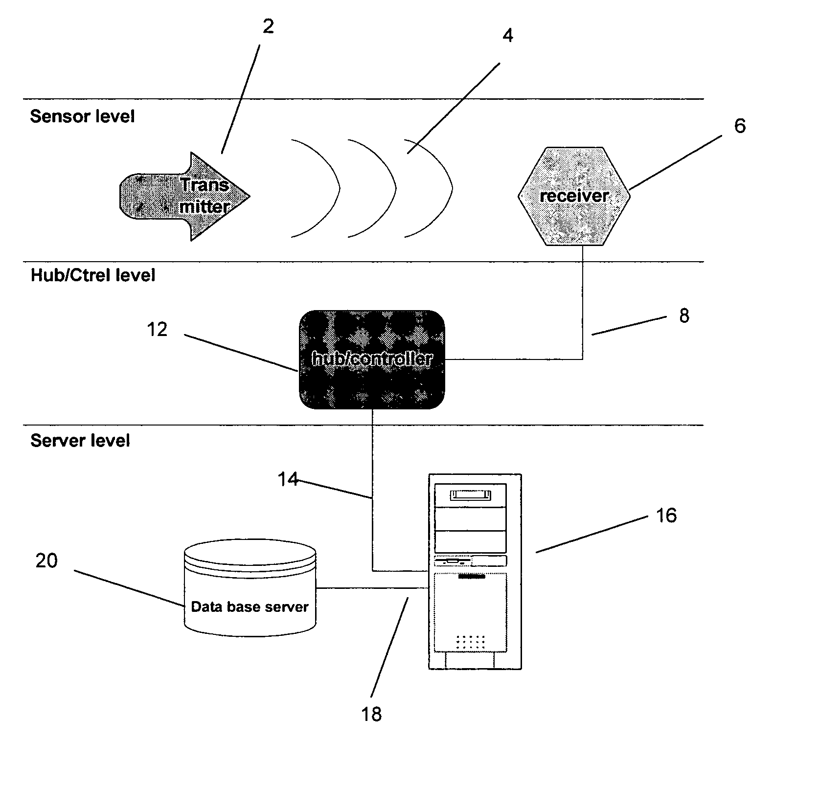
[0021] The invention provides an ultrasonic locator system and method. Preferred embodiments will now be described with reference to the drawing figures, in which like reference numerals refer to like parts throughout.

[0022] Ultrasound can be used as a signaling medium between a mobile transmitting device and a known receiving location. Since ultrasound travels at the speed of sound it is less difficult to take measurement of the distance traveled as compared to light. For example, in air at 20° C., normal atmospheric pressure (sea level), sound is known to travel at about 343 meters per second (approximately 1125 feet per second). Accordingly, the ultrasound wave travels at about 2.5 centimeters for every 73 microseconds, which is a time interval that is easily managed by the clock speed of conventional processing systems.

[0023] Ultrasound is also known to be bounded by floor and ceiling structures, and does not easily penetrate glass. Thus, ultrasound waves offers a reliable mea...


PUM


Abstract

An ultrasonic transmitter system(s) and method(s) are described having location and tracking capabilities. The transmitter's, by using ultra sound and encoded micro-modulation, are able to provide enhanced longevity and reliability. A maze algorithm is devised that further provides discrimination of false detections, versus true detections, and no detection.

Description

FIELD OF THE INVENTION [0001] The present invention relates generally to locator systems. More particularly, the present invention relates to a locator system and method using ultrasonic signals. BACKGROUND OF THE INVENTION [0002] Personnel or asset location systems are routinely used in manufacturing and hospital environments. However, with increasing concerns for security and inventory control, such systems have progressed beyond typical manufacturing and hospital environments to other areas such as, for example, government and corporate environments. [0003] In order to provide accurate location of the tracked object, a transmitter is commonly attached to the object. The transmitter stores information regarding the object's characteristic and routinely, or upon prompting, using various transmission methodologies transmits, for example, radio, ultrasonic, or optical signals to various receivers located within the tracking environment. Based on either time-difference of arrival info...

Claims


Application Information

Patent Timeline
Patent Type & Authority Applications(United States)
IPC IPC(8): G06K17/00G06K19/07G08B13/14
CPCG01S15/02G06K19/0723G08B13/14G06K2017/0045G06K19/0728
Inventor DROUIN, GUYPIUZE, JEAN-MARCLANDRY, FREDERIC
Owner ASCOM SWEDEN
Why Eureka
Try Eureka