Stabilizing motion in a radar detection system using ultrasonic radar range information

a radar detection and ultrasonic technology, applied in the field of microwave radar systems, can solve the problems that the homoodyne radar cannot effectively determine if the detected movement is detected, and the need for a solution in the industry has not yet been addressed, and achieve the effect of suppressing motion artifacts

Inactive Publication Date: 2005-06-16
GEORGIA TECH RES CORP
View PDF17 Cites 54 Cited by
  • Summary
  • Abstract
  • Description
  • Claims
  • Application Information

AI Technical Summary

Problems solved by technology

Thus, when hand motion is present, the homodyne radar cannot effectively determine if the detected movement signature is from the subject or from the stationary wall.
Thus, a heretofore unaddressed need exists in the industry to address the aforementioned deficiencies and inadequacies.

Method used


Image

  • Stabilizing motion in a radar detection system using ultrasonic radar range information
  • Stabilizing motion in a radar detection system using ultrasonic radar range information
  • Stabilizing motion in a radar detection system using ultrasonic radar range information

Examples


Embodiment Construction

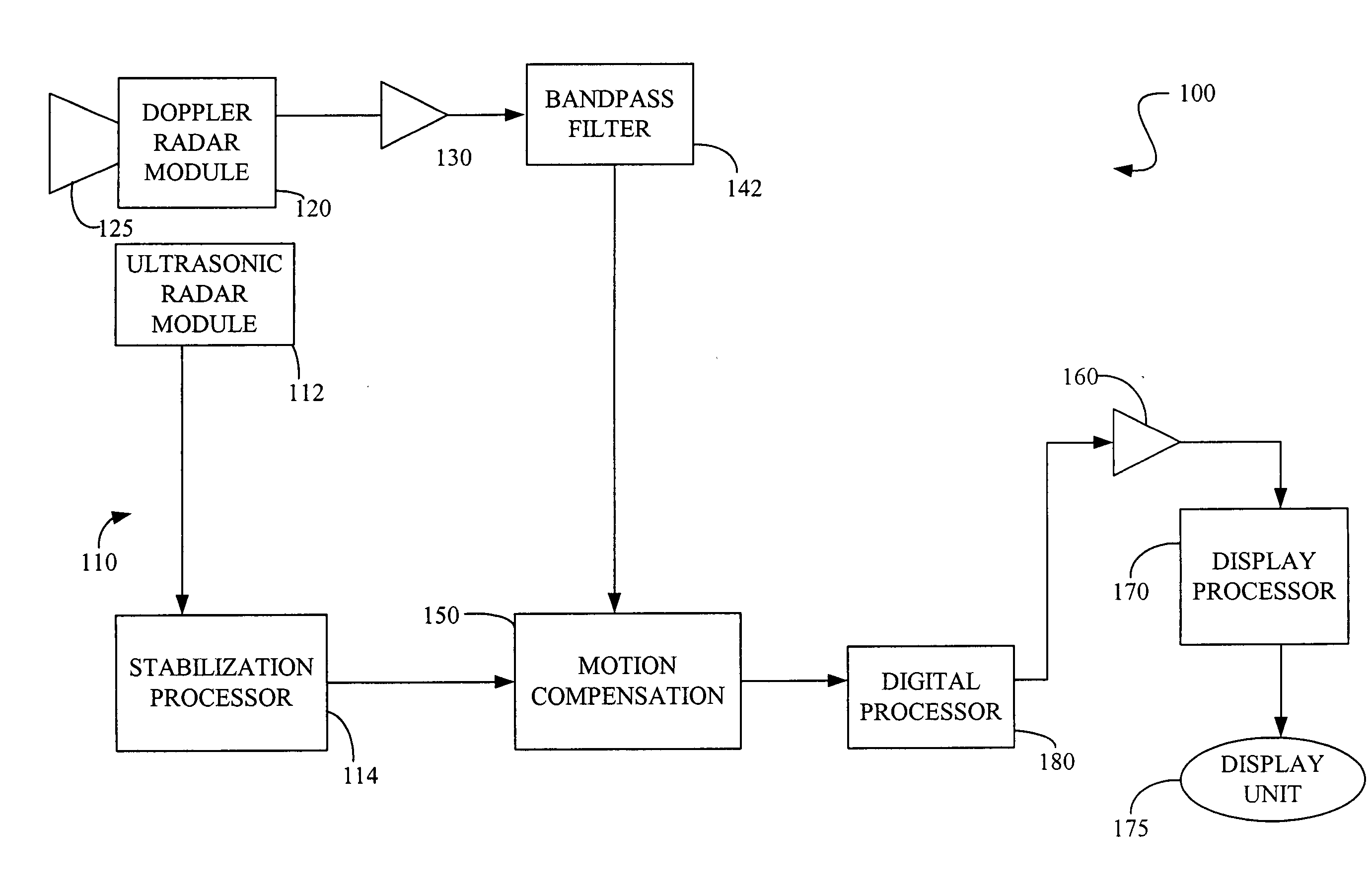
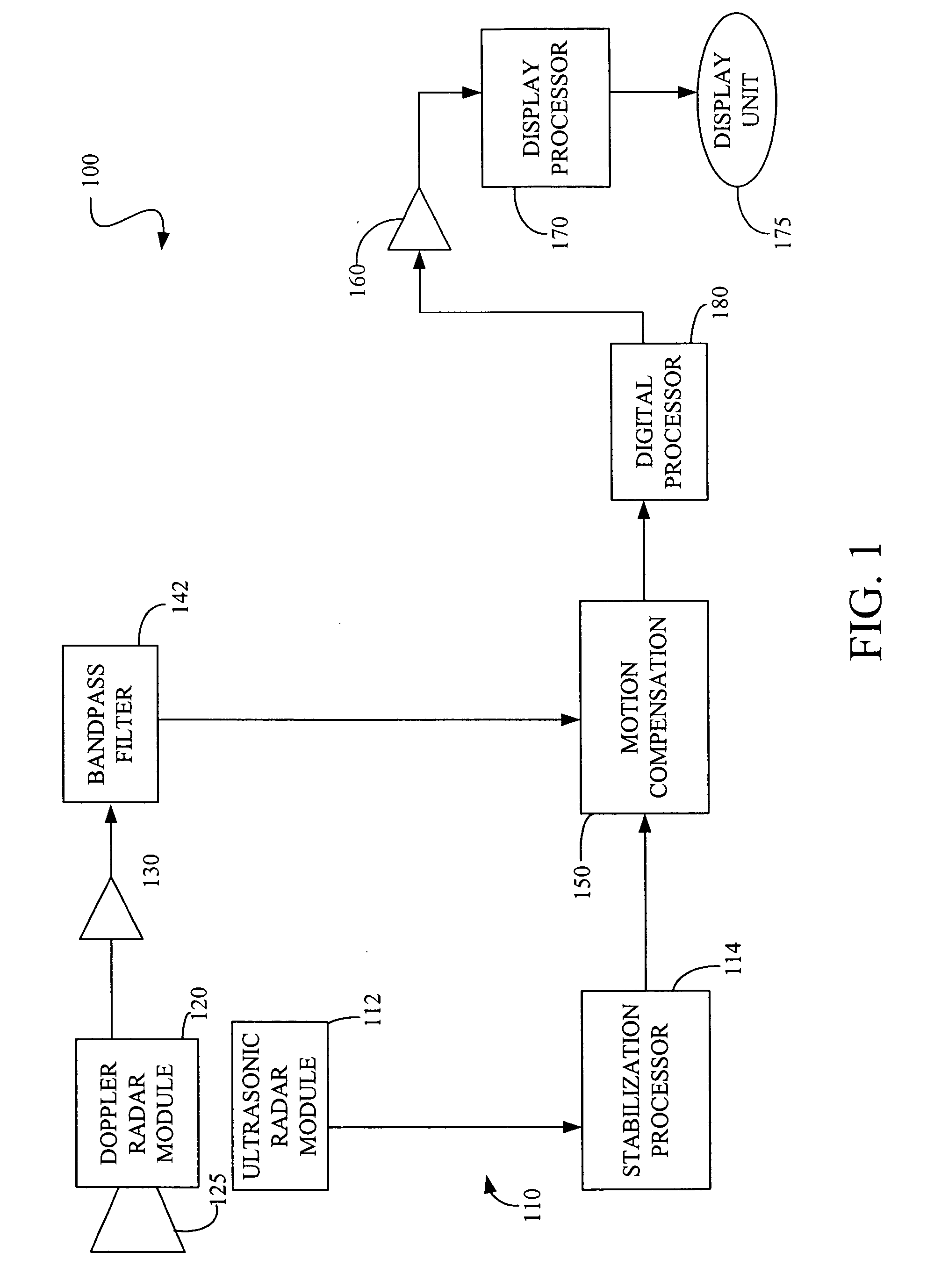
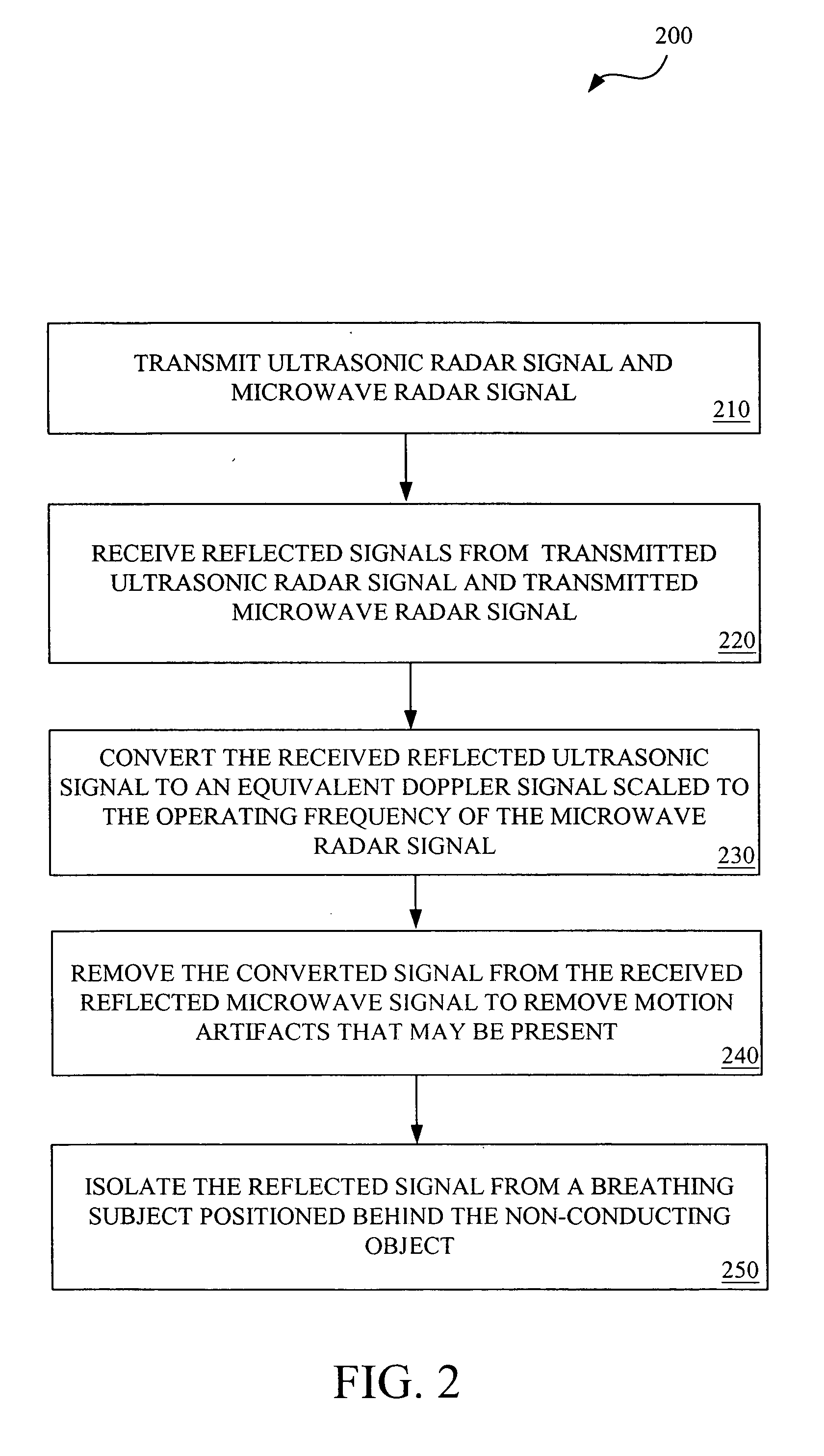
[0017]FIG. 1 shows a diagram of one embodiment of a radar detection device (100) employing one embodiment of the stabilization system (110) of the present invention. In this example, the radar detection device (100) comprises a Doppler radar module (120) that generates a microwave continuous wave (CW) signal at 10.525 GHz. However, other microwave frequencies may also be used.

[0018] The CW signal is generated using a solid state Gunn device transmitter (not shown). The resulting CW signal is transmitted through an antenna (125). When a person, for example, is located in front of the antenna (125), the transmitted signal is reflected off the body of the target individual. Thus, any motion of the person's body causes a phase shift in the reflected signal proportional to the amount of motion in the radial direction to the Doppler radar module (120). At a frequency of 10.525 GHz, for example, the typical phase shift is 360 degrees for every 1.75 centimeters of radial motion toward or w...


PUM


Abstract

One preferred embodiment of the present invention provides a system and method for suppressing motion artifacts introduced by movement of a radar detection system. Briefly described, in architecture, one embodiment of the system, among others, can be implemented as follows. The system includes a Doppler radar module configured to transmit a microwave signal directed towards an object and receive the reflected microwave signals from the object and a living subject positioned behind the object. Also, the system includes a reference module configured to transmit a reference signal towards the object and receive the reflected reference signal from the object. By comparing the two reflected signals from the Doppler radar module and the reference device, a signal processor suppresses motion artifacts generated by movement of the Doppler radar module to identify the presence of the living subject behind the object. Other systems and methods are also provided.

Description

TECHNICAL FIELD [0001] The present invention is generally related to microwave radar systems and, more particularly, is related to systems and methods for detecting vital signs, through a non-conducting intervening wall with a microwave radar system. BACKGROUND OF THE INVENTION [0002] One recent use of homodyne radar system involves the detection of minute body movements which are associated with human respiratory activity. This approach is based on the principle that breathing produces measurable phase changes in electromagnetic waves as they reflect off of the skin surface of the moving thorax of a living person. When the skin surface is moving, as does the surface of the chest in conjunction with respiratory and cardiac activities, corresponding variations will be observed in the difference of the phase between the received and transmitted signal. The observed variations can be used to determine motion-related target parameters such as displacement and velocity. [0003] Given the ...

Claims


Application Information

Patent Timeline
Patent Type & Authority Applications(United States)
IPC IPC(8): G01S7/40G01S13/56G01S13/86G01S13/88
CPCA61B5/0507G01S13/56G01S13/862G01S15/08G01S13/888
Inventor GRENEKER, EUGENE FERGUSON IIIZYWICKI, DAREN JOSEPH
Owner GEORGIA TECH RES CORP
Why Eureka
Try Eureka