Antenna device and radio communication apparatus using the antenna device

a radio communication apparatus and antenna technology, applied in the field of antenna devices, can solve the problems of improper array antenna radio communication apparatus deteriorating reception sensitivity, and improper antenna diversity technique for radio communication apparatus of the mobile type to be downsized, etc., to achieve the effect of suppressing the deterioration of reception sensitivity

Inactive Publication Date: 2005-06-16
NEC CORP
View PDF5 Cites 50 Cited by
  • Summary
  • Abstract
  • Description
  • Claims
  • Application Information

AI Technical Summary

Benefits of technology

[0013] The present invention has been made to solve the above problems, and therefore an object of the present invention is to suppress deterioration of_reception sensitivity by adaptively controlling antenna directivity even if its direction or inclination with respect to a base station is changed according to a use state of a radio communication apparatus. Also another object of the present invention is to attain a miniaturization without an antenna projecting from a radio communication apparatus.
[0023] In the antenna device constituted as described above, an electrical signal is fed from one terminal of the antenna element, and the other terminal of the antenna element is terminated by a variable reactance element of a lumped constant, to appropriately adjust an electric length of the antenna element, and also to make the antenna element length shorter than a predetermined value. Accordingly, there can be realized an antenna device relatively small in size and simple in structure.
[0024] In addition, because the antenna directivity can be readily controlled by adjusting the reactance value, the deterioration of reception sensitivity can be suppressed, and a communication quality can be improved.

Problems solved by technology

However, because the plurality of antenna elements is required to be mounted, the antenna diversity technique is improper for the radio communication apparatus of the mobile type to be downsized.
Also, the radio communication apparatus deteriorates the reception sensitivity even due to the absorption of electric waves into an approaching human body.
The array antenna technique is improper for the radio communication apparatus of the mobile type to be downsized because the antenna elements need to be arranged at given intervals, which leads to a large antenna device.
However, in order to change the directivity in a range of practical use, it is necessary to provide about 4 to 6 non-electricity-feed antenna elements, and therefore the above techniques are improper for the radio communication apparatus of the mobile type to be downsized.
The antenna device suffers from such a problem that the controllable directivity pattern is limited.
However, the controllable directivity is limited to two directions.
Therefore, the entire antenna device is relatively large in size, and it is difficult to incorporate the antenna device into the radio communication apparatus of the mobile type.
The conventional antenna devices as described above suffers from such problems that the directivity of the antenna is limited, and the number of antenna elements is increased, or the antenna per se becomes large in size.

Method used


Image

  • Antenna device and radio communication apparatus using the antenna device
  • Antenna device and radio communication apparatus using the antenna device
  • Antenna device and radio communication apparatus using the antenna device

Examples


first embodiment

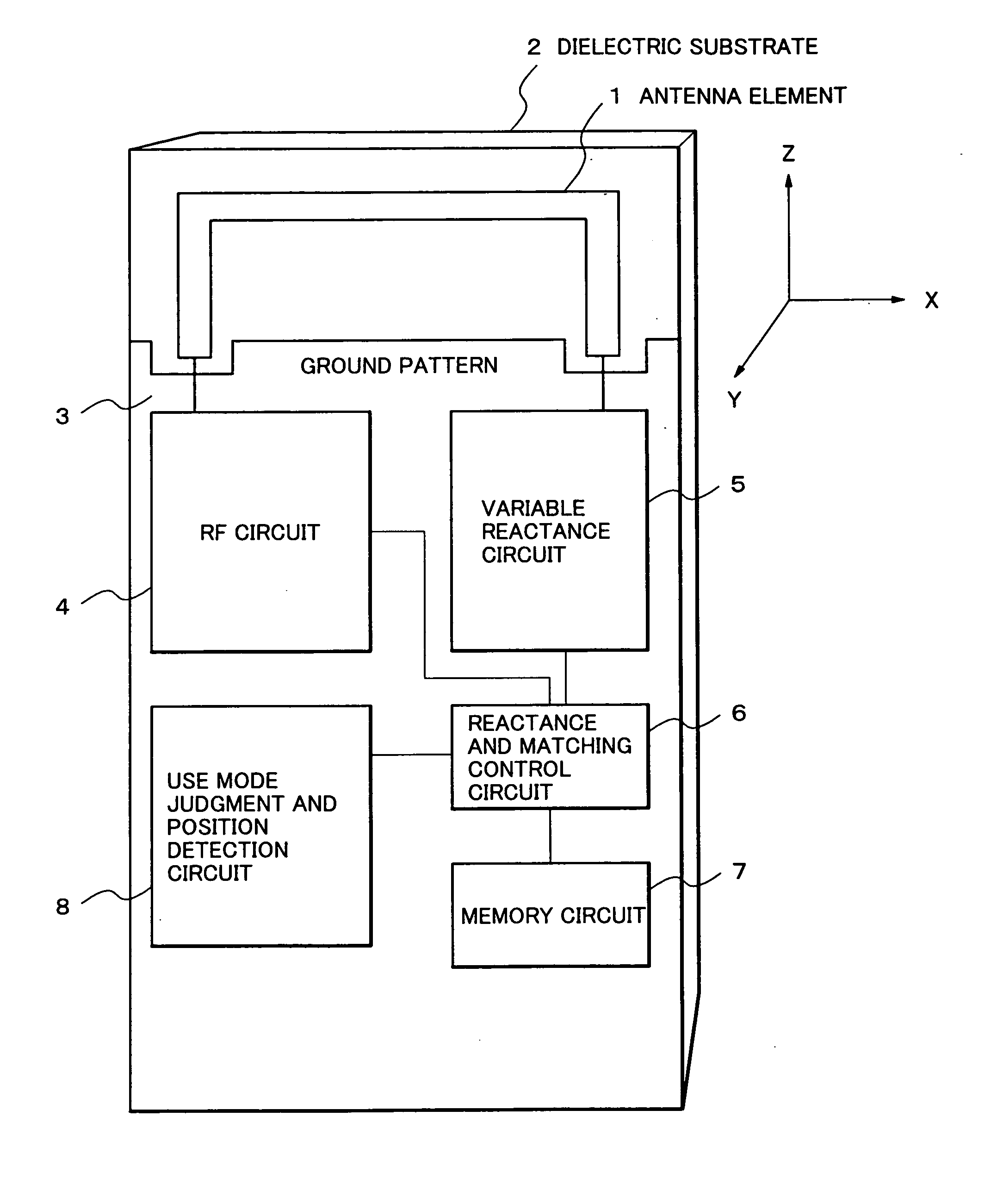
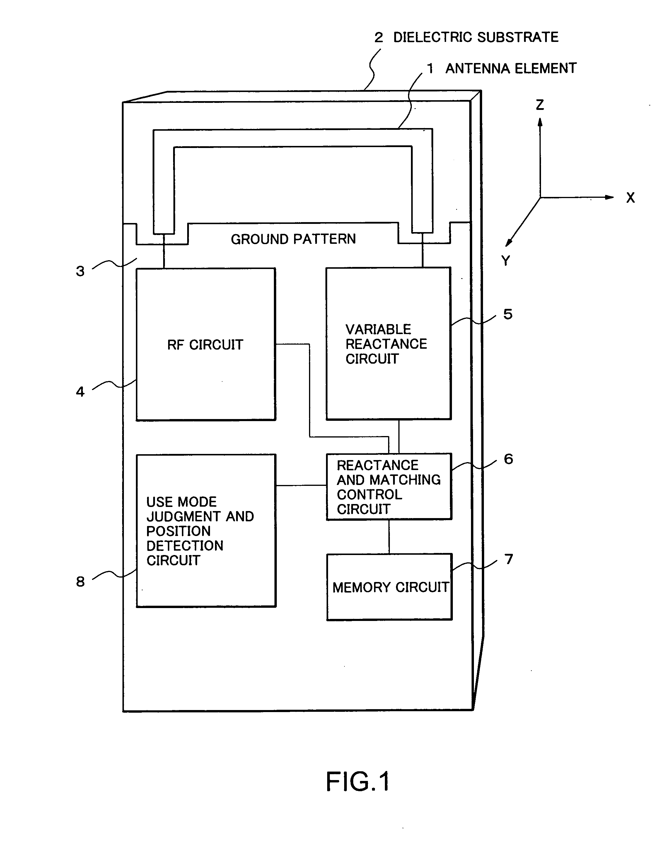
[0035]FIG. 1 is a conceptual diagram showing a construction of an antenna device according to a first embodiment of the present invention.

[0036] Referring to FIG. 1, the antenna device according to the first embodiment of the present invention includes an antenna element 1, an RF (radio frequency) circuit 4, a variable reactance circuit 5, a reactance and matching control circuit 6, a use mode judgment and position detection circuit 8, and a memory circuit 7. Also, those respective circuits are formed on a dielectric substrate 2 and integrated with each other.

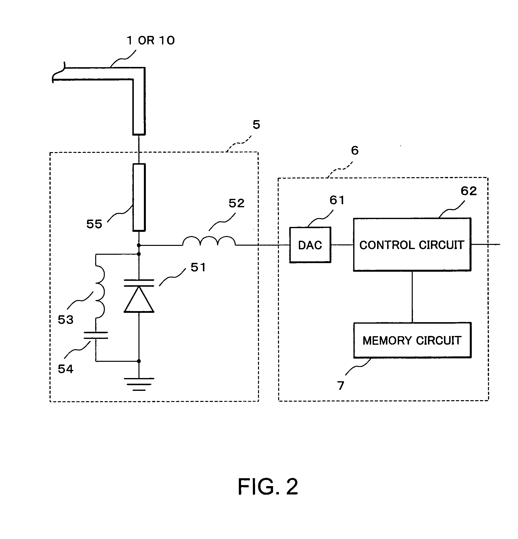
[0037] Then, an operation of the respective sections of the antenna device according to this embodiment will be described with reference to the accompanying drawings. FIG. 2 is a block diagram showing a structural example of the variable reactance circuit and the reactance and matching control circuit shown in FIG. 1. FIG. 3 is a circuit diagram showing another structural example of the variable reactance circuit shown in FIG...

second embodiment

[0062] Next, an antenna device according to a second embodiment of the present invention will be described. FIG. 5 is a conceptual diagram showing a construction of the antenna device according to the second embodiment of the present invention.

[0063] In FIG. 5, the antenna device is different from that in FIG. 1 in that the antenna element 1 is divided into antenna elements 9 and 10. In the antenna element 1 shown in FIG. 1, because an electrical signal is fed from one terminal of the antenna element 1, and the other terminal of the antenna element 1 is terminated by the reactance element, in the case where element length is shorter, the resonance frequency of the antenna element 1 does not coincide with the use frequency, and the impedance matching at the electricity feeding point is difficult.

[0064] As shown in FIG. 5, the antenna device according to the second embodiment is of a two-element structure in which the antenna element 1 shown in FIG. 1 is divided into the two L-shape...

third embodiment

[0066] Next, an antenna device according to a third embodiment of the present invention will be described. FIG. 6 is a conceptual diagram showing a construction of the antenna device according to the third embodiment of the present invention.

[0067] In FIG. 6, the antenna device is different from that in FIG. 1 in that a part of the antenna element 1 is transposed to a meandering line 11. In this case, element length occupied in an actual area can be shorter by transposing a portion or all on a straight line-like to meandering line 11. Other constructions are identical with those in the first embodiment, and therefore their description will be omitted.


PUM


Abstract

An electrical signal is fed from one terminal of an antenna element, and the other terminal thereof is terminated by a variable reactance circuit. A reactance value of the variable reactance circuit is changed according to use state of a device to optimally set its directivity. Matching conditions at an electricity feeding point are controlled to match an impedance of the electricity feeding point which fluctuates according to the value of the variable reactance circuit. With the above construction, there are provided an antenna device that is downsized, can control its directivity, and does not deteriorate a communication quality depending on a use state, and a radio communication apparatus provided with the antenna device.

Description

BACKGROUND OF THE INVENTION [0001] 1. Field of the Invention [0002] The present invention relates to an antenna device suitably used in a radio communication apparatus such as a cellular phone, or a radio communication apparatus such as a WLAN (wireless local area network) or an RFID (radio frequency identification). [0003] 2. Description of the Related Art [0004] In recent mobile communication systems, various services other than a telephone call have been under study such as data communication or TV telephone using web browsing, a position information detection service using a GPS (global positioning system), or authentication and accounting using the RFID (radio frequency identification). [0005] With the above study, the radio communication apparatus such as the cellular phone has been demanded to have a large number of functions in order to deal with various services. In addition, the radio communication apparatus has been demanded to stabilize the communication quality irrespec...

Claims


Application Information

Patent Timeline
Patent Type & Authority Applications(United States)
IPC IPC(8): H01Q23/00H01Q1/24H01Q1/38H01Q7/00H01Q9/04H01Q9/30H03H7/38H04B7/08H04M1/00H04M1/725
CPCH01Q1/242H01Q7/005H01Q3/00H01Q1/38
Inventor FUKUDA, JUNICHI
Owner NEC CORP
Why Eureka
Try Eureka