

Position detecting apparatus and position pointer
- Summary
- Abstract
- Description
- Claims
- Application Information
AI Technical Summary
Benefits of technology
Problems solved by technology
Method used
Image

Examples
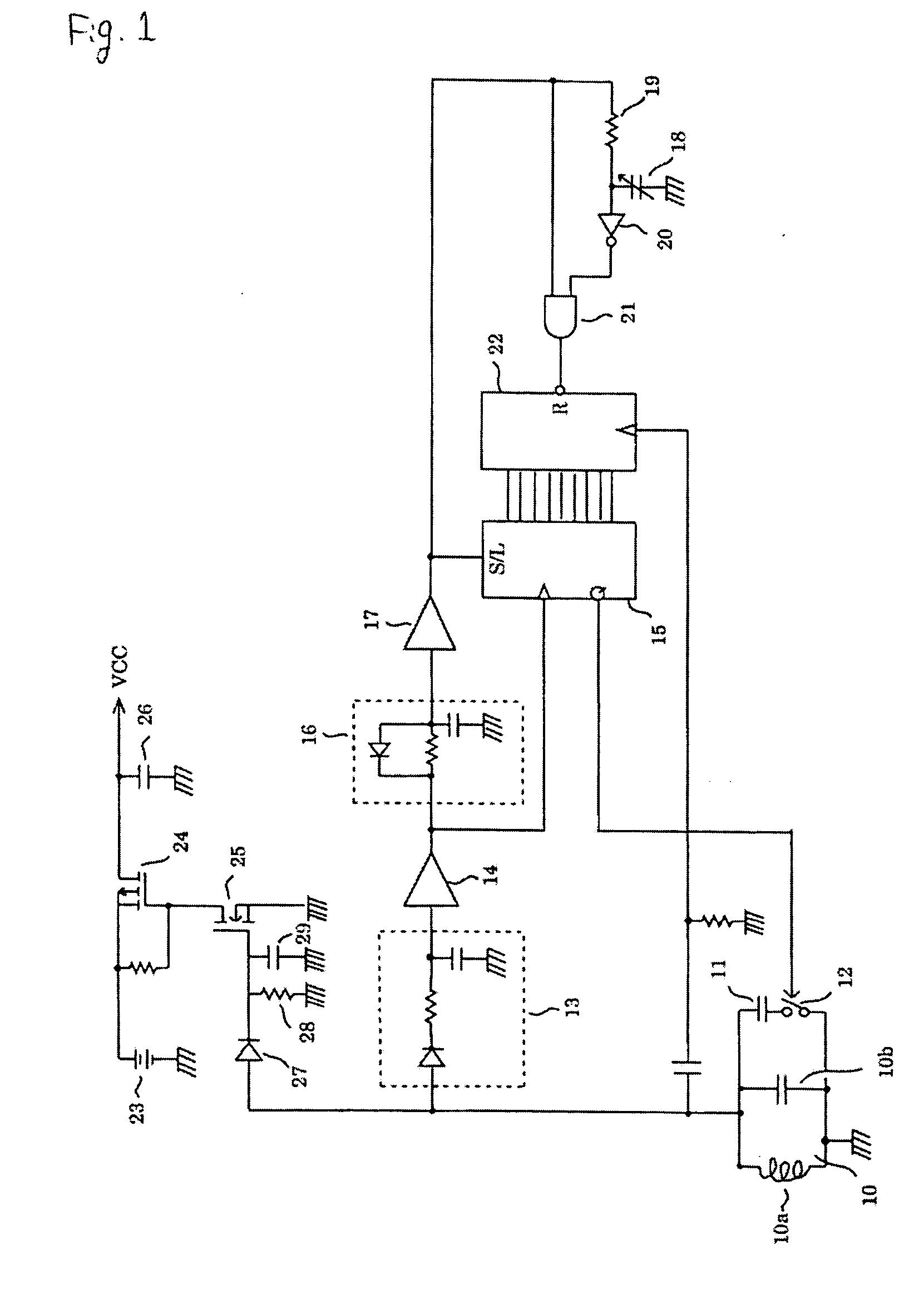
first embodiment
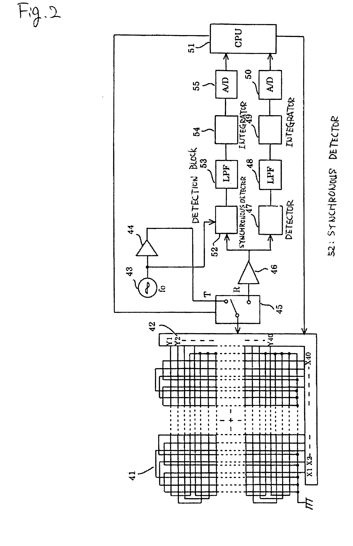
[0047]FIG. 2 is a block diagram showing a configuration of the tablet of the position detecting apparatus according to the present invention.
[0048] In FIG. 2, a loop coil set (loop sensor set) 41 serving as sensor means is disposed such that loop coils X1 to X40 are arranged in an X direction and loop coils Y1 to Y2 are arranged in a Y direction. The loop coils X1 to X40 and Y1 to Y40 are connected to a selector 42 for selecting a loop coil.
[0049] An oscillator 43 oscillates at a frequency of fo equal to the resonant frequency of the resonant circuit 10 of the position pointer. The oscillator 43 is connected to a transmission terminal (T) of a duplexer 45 via a current driver 44. The selector 42 is connected to a common terminal of the duplexer 45 such that an electromagnetic wave with a frequency of fo is radiated from a selected loop coil to the position pointer.
[0050] A reception terminal (R) of the duplexer 45 is connected to an amplifier 46 that is connected to a detector cir...
second embodiment
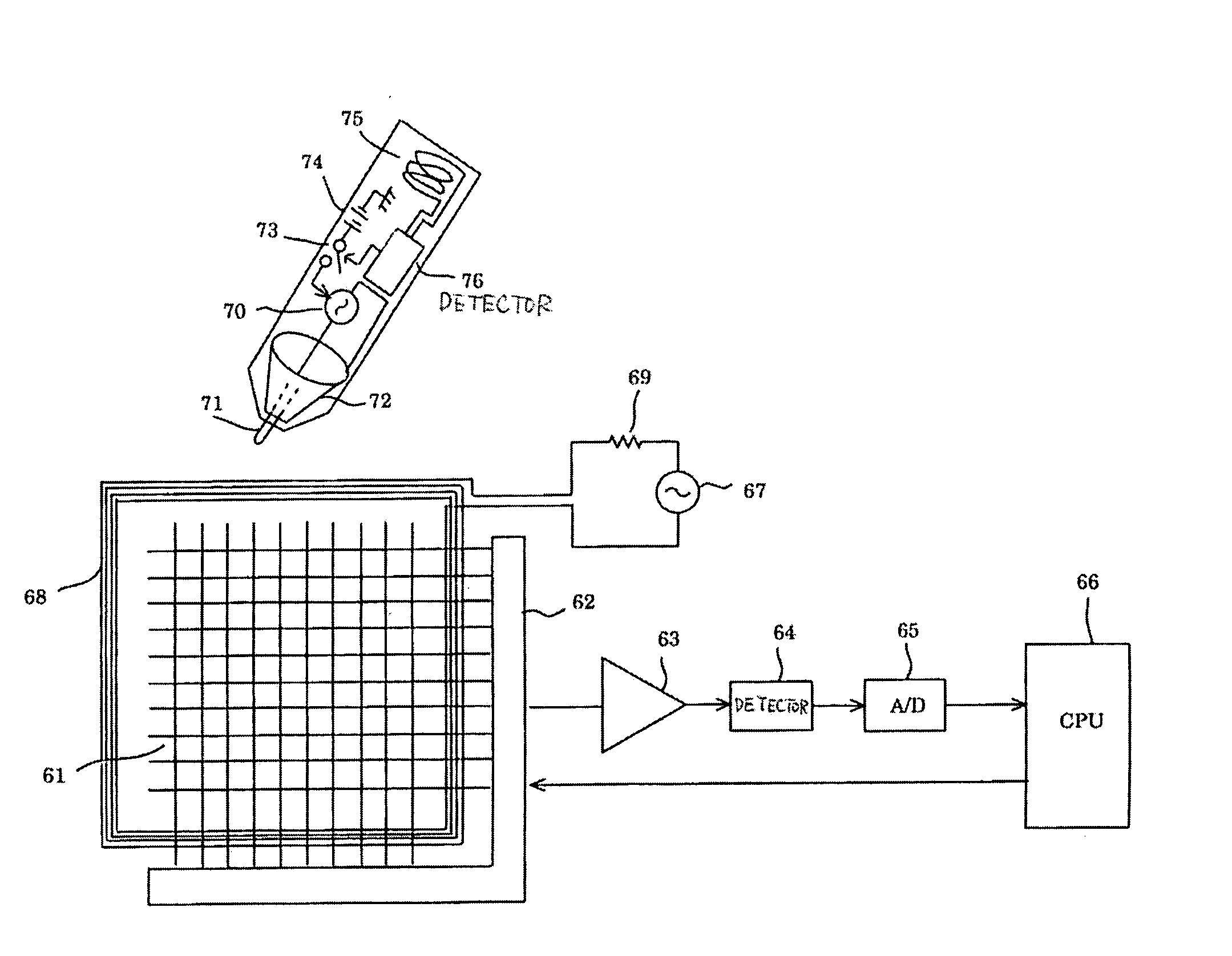
[0067] A position detecting apparatus according to the present invention will now be described.
[0068]FIG. 4 is a block diagram showing a configuration of a position pointer of the position detecting apparatus according to the second embodiment of the invention. In this second embodiment, a position pointed to by the position pointer is detected using electrostatic coupling.
[0069] In FIG. 4, sense lines (linear sensors) 61 serving as sensor means for detecting a high-frequency electric field radiated from a position pointer (that will be described in detail later) are disposed such that they extend in both vertical and horizontal directions and such that they are equally spaced. The sense lines 61 are connected to a selector 62 that selects one or two or more adjacent lines from the sense lines 61.
[0070] The one or more sense lines selected by the selector 62 are connected to an amplifier 63. An output of the amplifier 63 is connected to a detector 64. An output of the detector 64 ...
PUM
 Abstract
Description
Claims
Application Information