
Liquid crystal display

Inactive Publication Date: 2005-06-16
SHARP KK
View PDF8 Cites 14 Cited by
  • Summary
  • Abstract
  • Description
  • Claims
  • Application Information

AI Technical Summary

Benefits of technology

[0012] Therefore, an object of the present invention is to provide a liquid crystal display capable of preventing a color-tint phenomenon occurring during display of black while keeping whiteness at its any desired level.
[0013] The above object is achieved by a liquid crystal display including: a plurality of color pixels formed on a substrate; an opposing substrate placed on an opposite side of the substrate; a liquid crystal sealed between the substrate and the opposite substrate; and a control factor for reducing the color level difference between chromaticity during display of black and chromaticity during display of white, by varying transmissivity on a color pixel basis.
[0014] According to the present invention, realized is a liquid crystal display capable of preventing a color-tint phenomenon occurring during display of black while keeping whiteness at any desired level.

Problems solved by technology

The issue here is that even if whiteness is optimized though such adjustment, it does not necessarily optimize chromaticity during display of black (blackness).
However, merely adjusting whiteness does not achieve such match between blackness and whiteness, causing color level difference (chromatic deviation).
An adjustment optimizing blackness while keeping whiteness at its optimum level is extremely difficult.
The problem of such a multigap structure is that if blackness shows a bias toward green or red with respect to whiteness, the color tint cannot be reduced sufficiently.
Moreover, even if any desired whiteness is derived through adjustment of the color level balance of the color filters provided for every color pixel, and even if the color resists are provided with the same material contrast value, the color level during display of black may not be the desired level due to color-tinting caused by the polarization plate, color-tinting caused by the liquid crystal molecule alignment, or other reasons.
What is worse, depending on the panel structure, some specific color pixel region may suffer from liquid crystal molecule misalignment.
As a result, in such a color pixel region, the transmissivity is increased during display of black, thereby causing color-tint.
As such, the larger color level difference causes color-tint during display of black, and this is a cause of considerably lowering the display quality as the liquid crystal display.

Method used


Image

  • Liquid crystal display
  • Liquid crystal display
  • Liquid crystal display

Examples


first embodiment

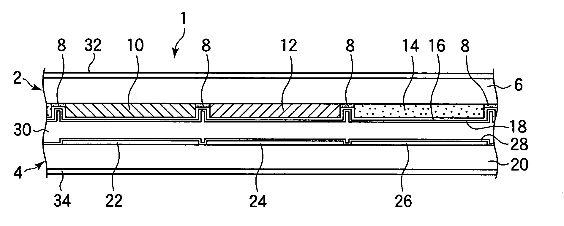
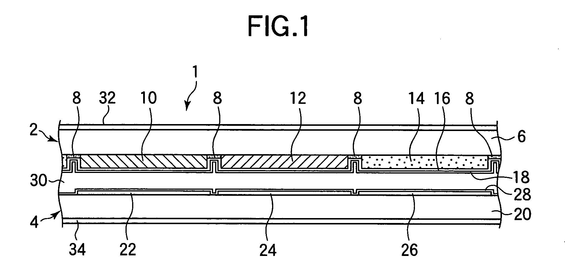
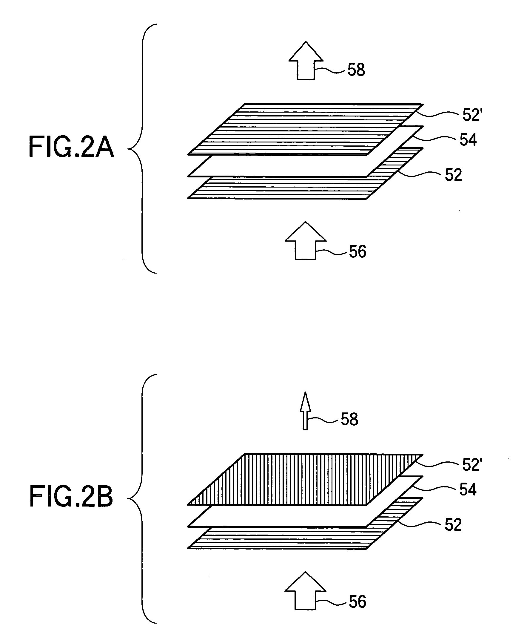
[0021] A liquid crystal display according to a first embodiment of the present invention is described by referring to FIG. 1 to 3. The present embodiment is characterized in that, in the liquid crystal display, the color level difference between whiteness and blackness is reduced by adjusting blackness through control of transmissivity during display of black on a color pixel basis. In an exemplary case where blackness shows a bias toward red with respect to whiteness, i.e., in x-y chromaticity coordinates, the x coordinate value for blackness is larger than that for whiteness, reducing the transmissivity of a red pixel is a possibility during display of black. Alternatively, the x coordinate value for blackness may be reduced by increasing the transmissivity for green and blue pixels during display of black to bring blackness closer in level to whiteness. If this is the case, because such transmissivity reduction is applied only during display of black, the influence on whiteness c...

second embodiment

[0037] By referring to FIGS. 4A and 4B, a liquid crystal display according to a second embodiment of the present invention is described. FIGS. 4A and 4B both show the schematic structure of color pixels (red pixel 10, green pixel 12, and blue pixel 14) in the liquid crystal display 1 of the present embodiment. Specifically, FIG. 4A shows the color pixels viewed from the image display surface of the CF substrate 2, and FIG. 4B shows the cross-section structure cut along a line A-A of FIG. 4A. Herein, any component identical in operation and function as that of the liquid crystal display 1 of FIG. 1 of the first embodiment is provided with the same reference numeral, and not described again.

[0038] As shown in FIGS. 4A and 4B, the liquid crystal display 1 is characterized in that a resin protrusion 36 is provided on the blue pixel 14 as a control factor for reducing the color level difference between whiteness and blackness. The resin protrusion 36 is partially a pillar resin spacer t...

third embodiment

[0040] By referring to FIGS. 5A and 5B, a liquid crystal display according to a third embodiment of the present invention is described. FIGS. 5A and 5B both show the schematic structure of color pixels (red pixel 10, green pixel 12 and blue pixel 14) in the liquid crystal display 1 of the present embodiment. Specifically, FIG. 5A shows the CF substrate 2 viewed from the image display surface, and FIG. 5B shows the cross-section structure cut along a line B-B of FIG. 5A. Herein, any component identical in operation and function as that of the liquid crystal display 1 of FIG. 1 of the first embodiment is provided with the same reference numeral, and not described again.

[0041] As shown in FIGS. 5A and 5B, the liquid crystal display 1 is characterized in that control factors for reducing the color level difference between whiteness and blackness are alignment control protrusions 40a, 40b, 42a, 42b, 44a and 44b. These alignment control protrusions 40a to 44b are all provided for alignme...


PUM


Abstract

In order to suppress color tint during display of black, chromaticity is changed when black is displayed while maintaining chromaticity when white is displayed. For this purpose, the pigment to be dispersed in a color resist is adjusted in particle size and concentration. Such adjustment is so performed that the chromaticity difference between displayed white and black becomes 0.01 or smaller in the x-y chromaticity coordinates by varying the transmissivity of color pixels during display of black. With such a structure, successfully provided is a color liquid crystal display capable of preventing color tint in displayed black, while keeping white chromaticity at the desired level.

Description

BACKGROUND OF THE INVENTION [0001] 1. Field of the Invention [0002] The present invention relates to a liquid crystal display capable of color display for use in a display section of an information appliance and others. [0003] 2. Description of the Related Art [0004] A liquid crystal display is provided with a pair of substrates each having a transparent electrode on the sides facing each other, and a liquid crystal layer sealed between these substrates. Through voltage applied between the transparent electrodes, the liquid crystal display drives the liquid crystal to control the light transmissivity of the liquid crystal on a pixel basis. In recent years, the liquid crystal display is used as a display section for a notebook PC, a television receiver, a display monitor, a PDA (Personal Digital Assistant), a projection projector, and others. The demand for the liquid crystal display has been increasing, accompanied with higher expectations therefor. Especially, improvement of the di...

Claims


Application Information

Patent Timeline
IPC IPC(8): G02B5/20G02F1/13G02F1/1333G02F1/1335G02F1/1337G02F1/1339G02F1/136
CPCG02F1/133512G02F2001/133776G02F1/133707G02F1/133776G02F1/1335
Inventor TANOSE, TOMONORISAWASAKI, MANABU
Owner SHARP KK
Learn More