Differential optical technique for chiral analysis

a chiral analysis and optical technique technology, applied in the field of chiral detectors, can solve the problems of affecting the polarisation of the detector, and the researcher cannot generally apply a high-throughput enantiomeric purity screening method, so as to improve the sensitivity, reduce noise, and improve the effect of optical rotation

Inactive Publication Date: 2005-06-16
STHENO
View PDF4 Cites 36 Cited by
  • Summary
  • Abstract
  • Description
  • Claims
  • Application Information

AI Technical Summary

Benefits of technology

[0008] A differential method has been developed which determines displacement from the midpoint of optical transmission (e.g., ±45°) and utilizes the coupled nature of the two signals for common mode noise rejection. The method and device may use lock-in detection with square wave modulation to reduce noise and improve sensitivity, may use new modulation techniques to achieve frequency modulation, may extend the technique to a multi-wavelength scanning mode, and may use a differential signal extraction mode to vastly improve sensitivity to optical rotation.

Problems solved by technology

Obtaining high enantiomeric purity of therapeutics is essential, since it is well known that the wrong enantiomer can cause harmful side effects.
Unfortunately, both of these activities remain significant challenges, even with the current state-of-the-art analytical instrumentation.
To date no generally applicable method for high throughput enantiomeric purity screening is available to the researcher.

Method used


Image

  • Differential optical technique for chiral analysis
  • Differential optical technique for chiral analysis
  • Differential optical technique for chiral analysis

Examples


Embodiment Construction

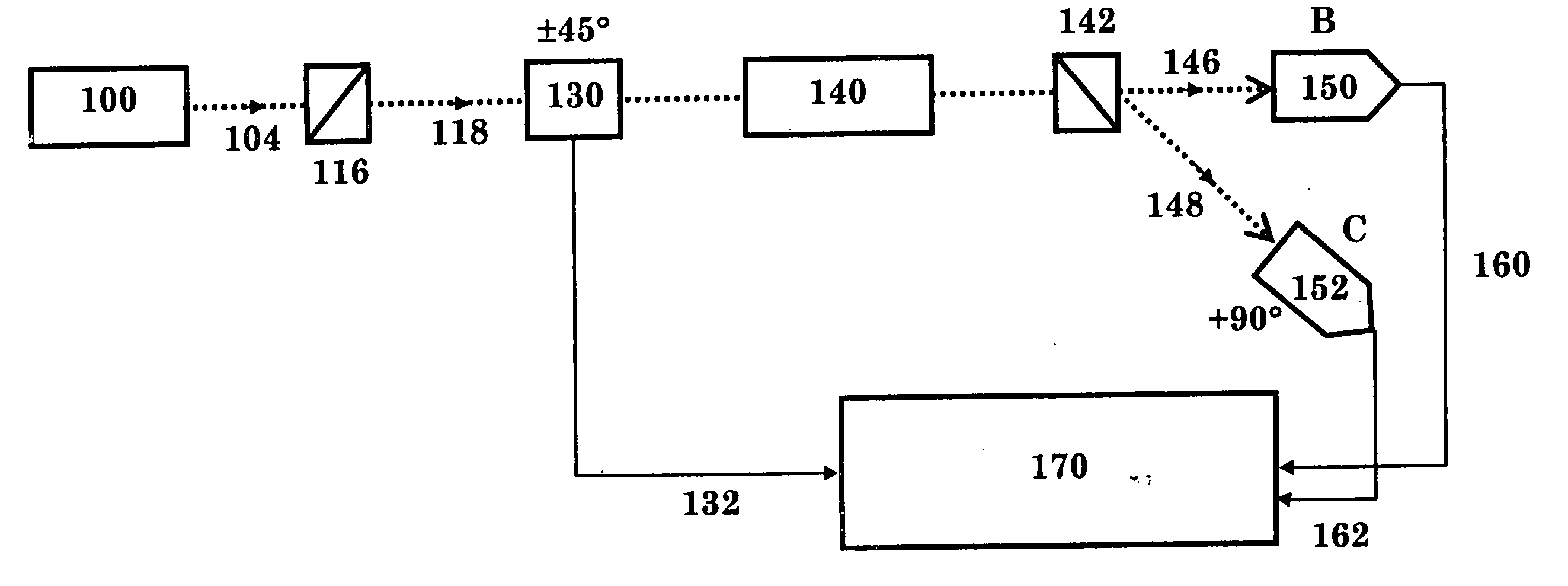
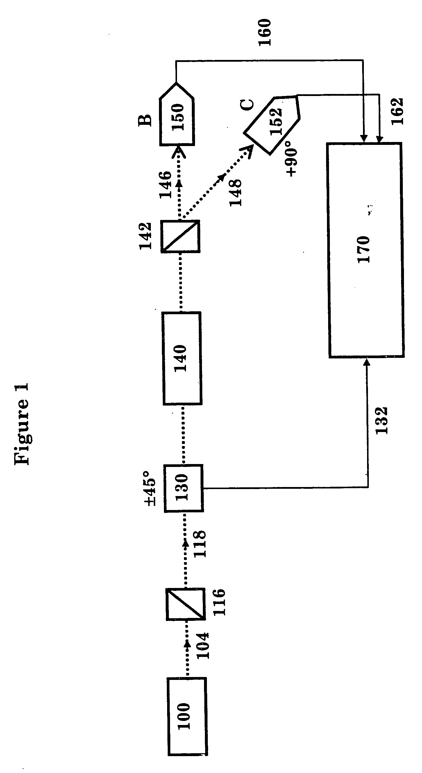
[0030] A block diagram of an embodiment of a basic differential optical rotary dispersion (DORD) apparatus in accordance with principles of the present invention is shown in FIG. 1. The basic apparatus includes light source 100, polarizer 116, signal modulator 130, sample cell 140, analyzer 142, a balanced photoreceiver (detectors B 150 and C152) and a lock in detector 170. The light source 100 can consist of a monochromatic source such as a laser, but a wider range of wavelengths provides more useful information. In a preferred embodiment, stabilized UV and tungsten lamps may be utilized to provide a bright broad wavelength source covering the approximate range 200 to 1100 nm when implementing the light source 100 with a Hamamatsu Model L7893 series lamp. A pulsed light source may be used to avoid ambiguities associated with intermediate polarizer positions. However, in practice a continuous light source can be used and the switching time of the signal modulator may be fast enough ...


PUM

PropertyMeasurementUnit
wavelength rangeaaaaaaaaaa
wavelengthaaaaaaaaaa
wavelength rangeaaaaaaaaaa

Abstract

A differential method has been developed which determines displacement from the midpoint of optical transmission (±45°) and utilizes the coupled nature of the two signals for common mode noise rejection to enhance the detection of chiral species. A beam of light is modulated, applied to the chiral mixture, and then split into a first beam and a related orthogonal beam by a polarizer or prism. The first beam and orthogonal beam are converted into electrical signals before a differential comparison of the signals is performed to detect a desired chiral species within the chiral mixture.

Description

RELATED APPLICATIONS [0001] This application hereby claims benefit to and incorporates by reference in their entirety earlier filed U.S. Provisional Patent Application Ser. No. 60 / 510,209, which was filed on Oct. 10, 2003 and U.S. Provisional Patent Application Ser. No. 60 / 563,364, which was filed on Apr. 19, 2004.STATEMENT REGARDING FEDERALLY SPONSORED RESEARCH [0002] The U.S. government has certain rights to this invention by virtue of Grant #0320299 from the National Science Foundation Grant to Phillip R. Gibbs.FIELD OF THE INVENTION [0003] The present invention relates to chiral detectors, more particularly to a differential optical rotary dispersion detector for non-contact, rapid, and accurate screening of chiral samples. BACKGROUND OF THE INVENTION [0004] Optical isomers, more commonly called enantiomers, are important in several fields, including the pharmaceutical, chemical, essential oils, flavor, and food industries. The vast majority of useful drugs contain one or severa...

Claims


Application Information

Patent Timeline
Patent Type & Authority Applications(United States)
IPC IPC(8): G01J4/00G01N21/19G01N21/21G02B
CPCG01N21/21G01N21/19
Inventor GIBBS, PHILLIP R.
Owner STHENO
Why Eureka
Try Eureka