Sealing arrangement for a rotor of a turbo machine

a technology of sealing arrangement and turbomachine, which is applied in the direction of liquid fuel engines, vessel construction, marine propulsion, etc., can solve the problems of gas leakage from the flow channels formed by component parts, loss of strength, and unnecessary heating, so as to improve the tightness of the connection and the security of the seal, the effect of minimizing the gap between the components and the sealing elements

Active Publication Date: 2005-06-16
ANSALDO ENERGIA IP UK LTD
View PDF11 Cites 21 Cited by
  • Summary
  • Abstract
  • Description
  • Claims
  • Application Information

AI Technical Summary

Benefits of technology

[0024] It can also be advantageous that the first and / or second sealing elements are positioned such that there is a substantially maximum mismatch between the circumferential positions of junctions between mutually adjacent sealing elements and the circumferential positions of junctions between mutually adjacent blades and / or heat shields.
[0025] The provision of such slots and correspondingly configured projections on the sealing element provides two degrees of freedom, because the arrangement accommodates both axial and radial movement between adjacent component parts. This in turn allows the minimum gap at the connection between the components and sealing elements to be minimized, thereby leading to a more fluid-tight seal. It is further the case that centrifugal forces in the running engine contribute to the effect by pressing the sealing element against a side of the slot in which it is situated, thereby improving the tightness of the connection and the security of the seal still further. It is further the case that the relative characteristics of the blade, heat shield and sealing elements facilitate a highly efficient and effective manufacturing process.

Problems solved by technology

It is a recognised problem that gases can leak from the flow channels formed by component parts, such as blade roots and heat shields, of a rotor in a turbomachine.
The effects of such leakage will depend upon the type of turbomachine, but include: unnecessary heating, a loss of strength, mechanical failure, a loss of efficiency and a need for undesirably expensive materials.
Whilst such arrangements have been successful in reducing gas leakage, they suffer from a disadvantage that the slots in the adjacent component parts need to be provided at the same radial level and implementation of this precondition requires the component parts to be manufactured to within extremely narrow tolerances.
It is further the case that the relative positions of the slots can change during operation of the turbomachine, due to the influences of high temperatures and centrifugal forces, with the effect that a plate can be subject to shear or to fracture.
However, in this case, the plates are positioned in their slots with a significant skew and this results in unsatisfactorily high levels of leakage past the seal.
When many joints are provided between individual sealing elements in the circumferential direction, the number of potential leakage paths tends to increase, with the effect that the problem is particularly exacerbated.

Method used


Image

  • Sealing arrangement for a rotor of a turbo machine
  • Sealing arrangement for a rotor of a turbo machine
  • Sealing arrangement for a rotor of a turbo machine

Examples


Embodiment Construction

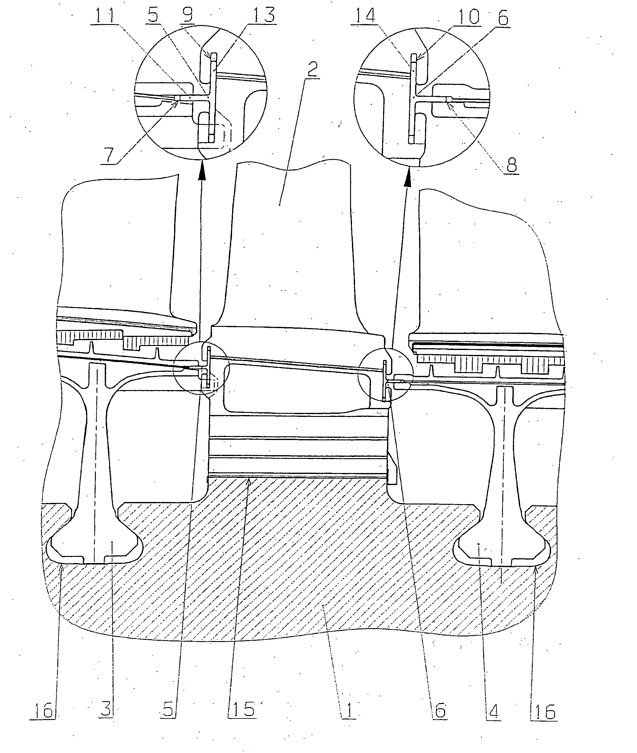
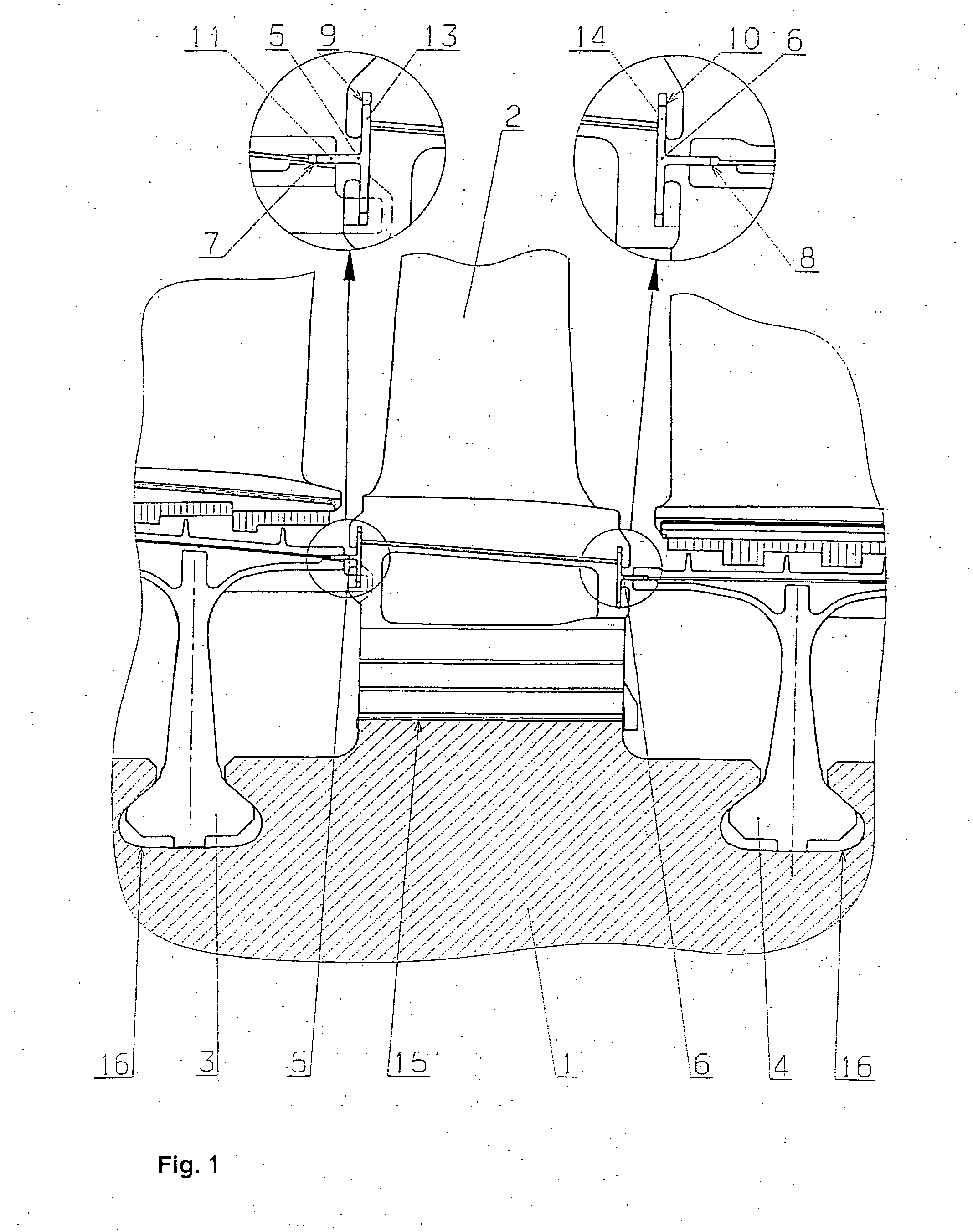
[0031]FIG. 1 shows part of a rotor defining an embodiment of the invention. The arrangement includes a rotor shaft 1, upon which are mounted a rotor blade 2 and heat shields 3, 4. This arrangement is replicated along the length of the rotor and around its circumference, however the following discussion will initially concentrate on the illustrated part for the sake of clarity.

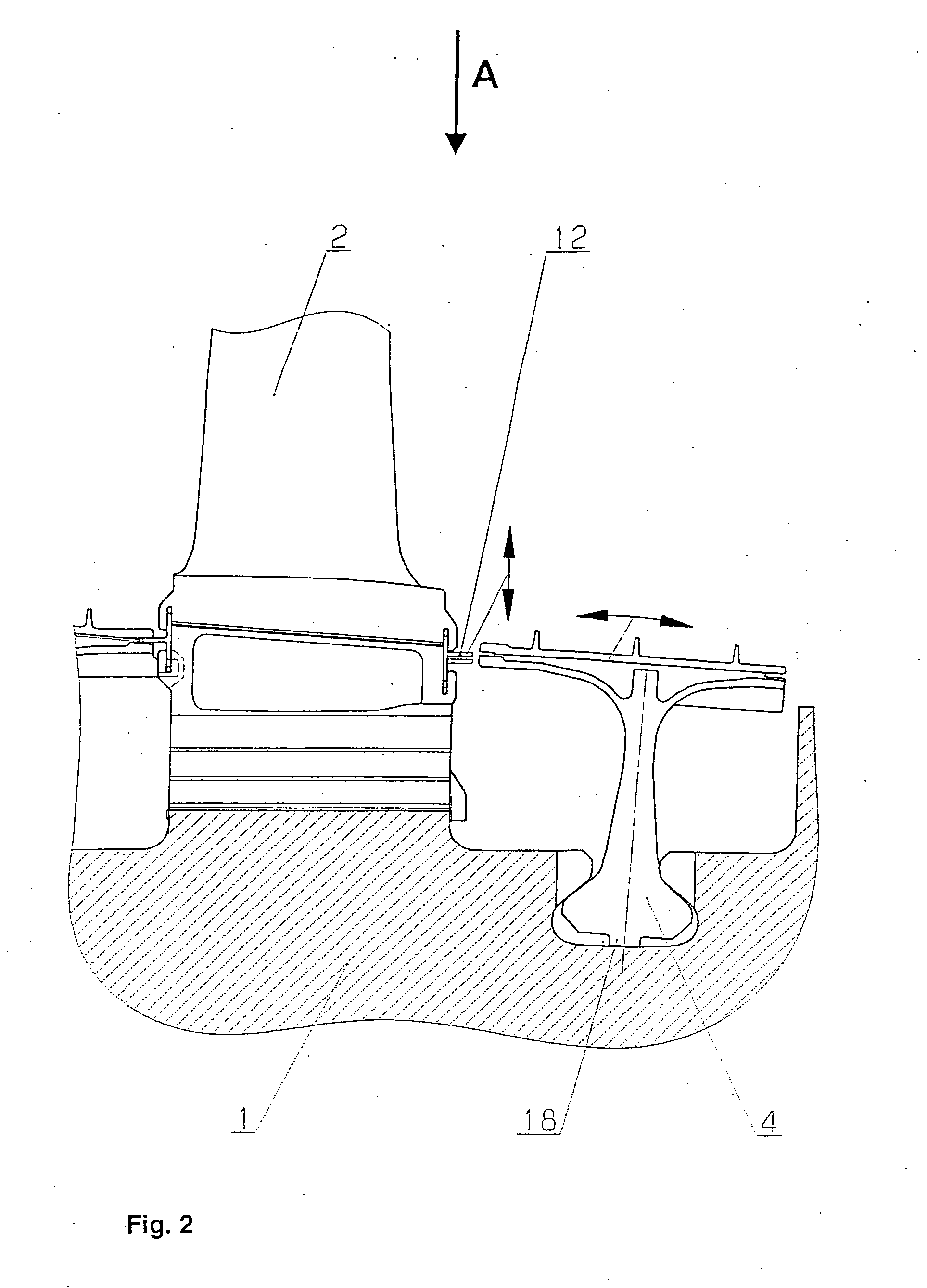
[0032] Each heat shield 3, 4 includes a root body portion 18 which is generally triangular in cross section, with radiussed corners. The slot 15, 16 for accommodating the root body is correspondingly configured, but of larger dimensions, so that the root body portion 18 may rock, to a limited degree, in the axial direction within the slot 16, as shown in FIG. 2. The shape and configurations of the blade and heat shields and their respective root portions are generally complex, but known. For this reason, they will not be described further in detail. The portions of the structure which are predominantly signifi...


PUM


Abstract

A sealing arrangement for a rotor of a turbomachine includes a blade (2), a heat shield (3, 4) and a sealing element (5, 6) for sealing between the blade (2) and the heat shield (3, 4) when the blade (2), heat shield (3, 4) and sealing element (5, 6) are assembled for use in the rotor. The heat shield (3, 4) includes a first slot (7, 8) for accommodating a first member (11, 12) of the sealing element (5, 6), and a root portion of the blade (2) includes a second and third slot (9, 10) for accommodating a second member (13, 14) of the sealing element (5, 6). The first slot (7, 8) extends in a direction which is substantially mutually perpendicular to a direction in which the second and third slot (9) extends, and the first member (11, 12) extends in a direction which is substantially mutually perpendicular to a direction in which the second member (13, 14) extends.

Description

[0001] This application is a Continuation of, and claims priority under 35 U.S.C. § 120 to, International Application number PCT / IB03 / 501866, by the inventors hereof, filed 21 May 2003, and claims priority to EPO application number 02405479.3, filed 11 Jun. 2002, the entireties of both of which are incorporated by reference herein.BACKGROUND OF THE INVENTION [0002] 1. Field of the Invention [0003] This invention relates to a sealing arrangement for a rotor of a turbomachine. More particularly, but not exclusively, the invention relates to a sealing arrangement which can be used in the rotor of a gas turbine. [0004] 2. Brief Description of the Related Art [0005] It is a recognised problem that gases can leak from the flow channels formed by component parts, such as blade roots and heat shields, of a rotor in a turbomachine. The effects of such leakage will depend upon the type of turbomachine, but include: unnecessary heating, a loss of strength, mechanical failure, a loss of efficie...

Claims


Application Information

Patent Timeline
Patent Type & Authority Applications(United States)
IPC IPC(8): F01D11/00
CPCF01D11/005F05B2230/606F01D11/008F01D11/006F05D2230/642
Inventor BEKRENEV, IGOR A.FOKINE, ARKADIHUMMEL, FRANKOSSIPOV, IGORTRIFONOV, SERGEY
Owner ANSALDO ENERGIA IP UK LTD
Why Eureka
Try Eureka