Electrochemical fuel cell stack having a plurality of integrated voltage reversal protection diodes

a technology of integrated diodes and fuel cell stacks, which is applied in the direction of electrochemical generators, cell components, cell component details, etc., can solve the problems of increasing the absolute potential of the fuel cell anode, affecting the quality of the fuel cell, and potentially subjecting unwanted voltage reversals of power-producing electrochemical fuel cells connected in series

Inactive Publication Date: 2005-06-16
BDF IP HLDG
View PDF4 Cites 7 Cited by
  • Summary
  • Abstract
  • Description
  • Claims
  • Application Information

AI Technical Summary

Problems solved by technology

However, power-producing electrochemical fuel cells connected in series are potentially subject to unwanted voltage reversals, as is the case when one of the cells is forced to the opposite polarity by the other cells in the series.
Aside from the loss of power associated with one or more cells going into voltage reversal, this situation poses durability and reliability concerns as well.
Undesirable electrochemical reactions may occur, which may detrimentally affect, or degrade, fuel cell components.
For example, when there is an inadequate supply of fuel (e.g., fuel starvation due to water flooding at the anode, fuel supply problems, and the like) to a SPE fuel cell, there can be a rise in the absolute potential of the fuel cell anode leading to the electrolysis of water present at the anode and oxidation (e.g., corrosion) of the anode components.
Such component degradation reduces the reliability and performance of the affected fuel cell, and in turn, its associated stack and array.
Sufficiently high voltages on the anode can also lead to electrical shorting in the cell.
With sufficient heating, the membrane melts resulting in the formation of holes and shorting of the cell.
However, since fuel cell stacks typically employ numerous fuel cells, such approaches can be quite complex and expensive to implement.

Method used


Image

  • Electrochemical fuel cell stack having a plurality of integrated voltage reversal protection diodes
  • Electrochemical fuel cell stack having a plurality of integrated voltage reversal protection diodes
  • Electrochemical fuel cell stack having a plurality of integrated voltage reversal protection diodes

Examples


Embodiment Construction

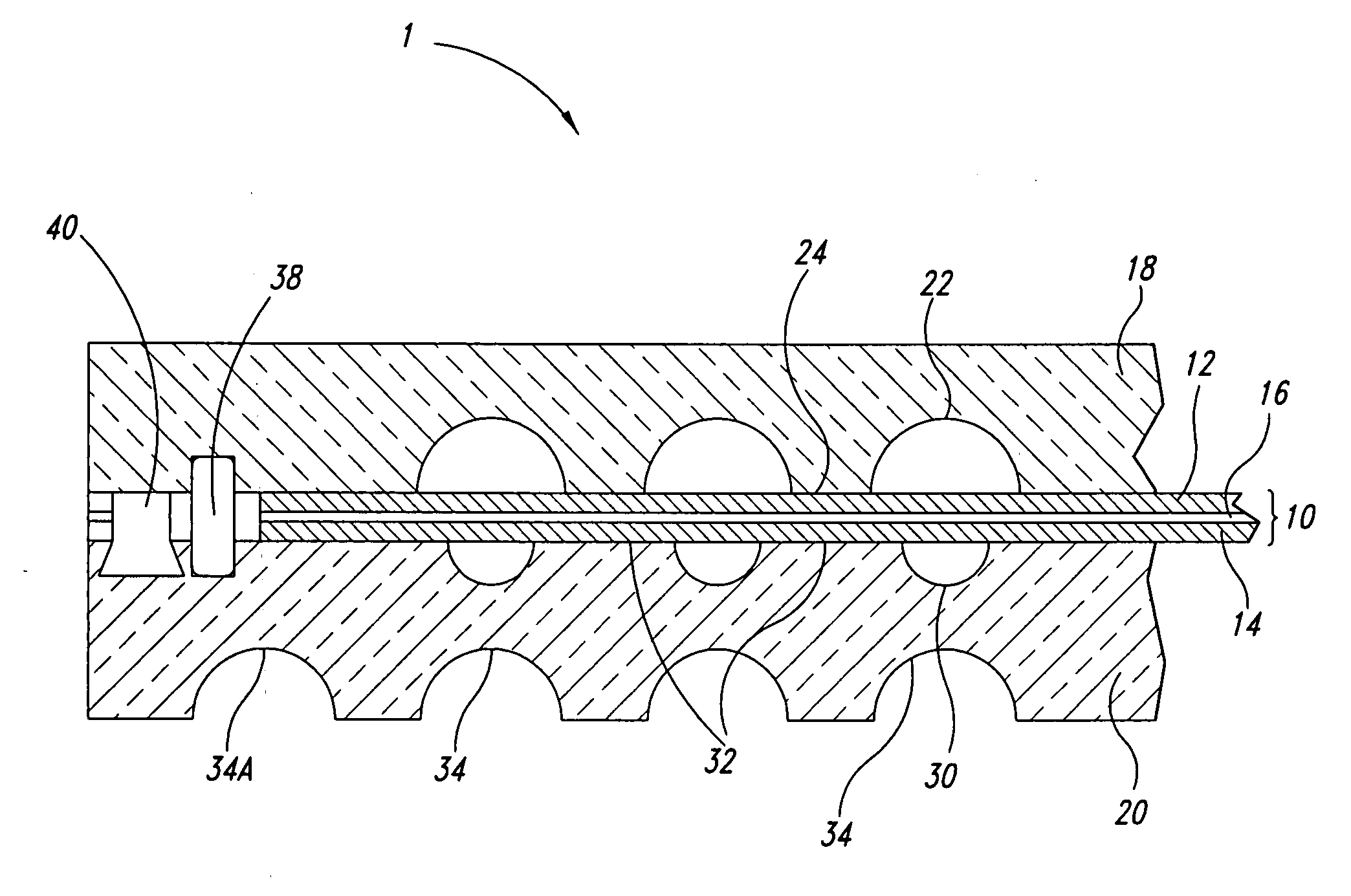
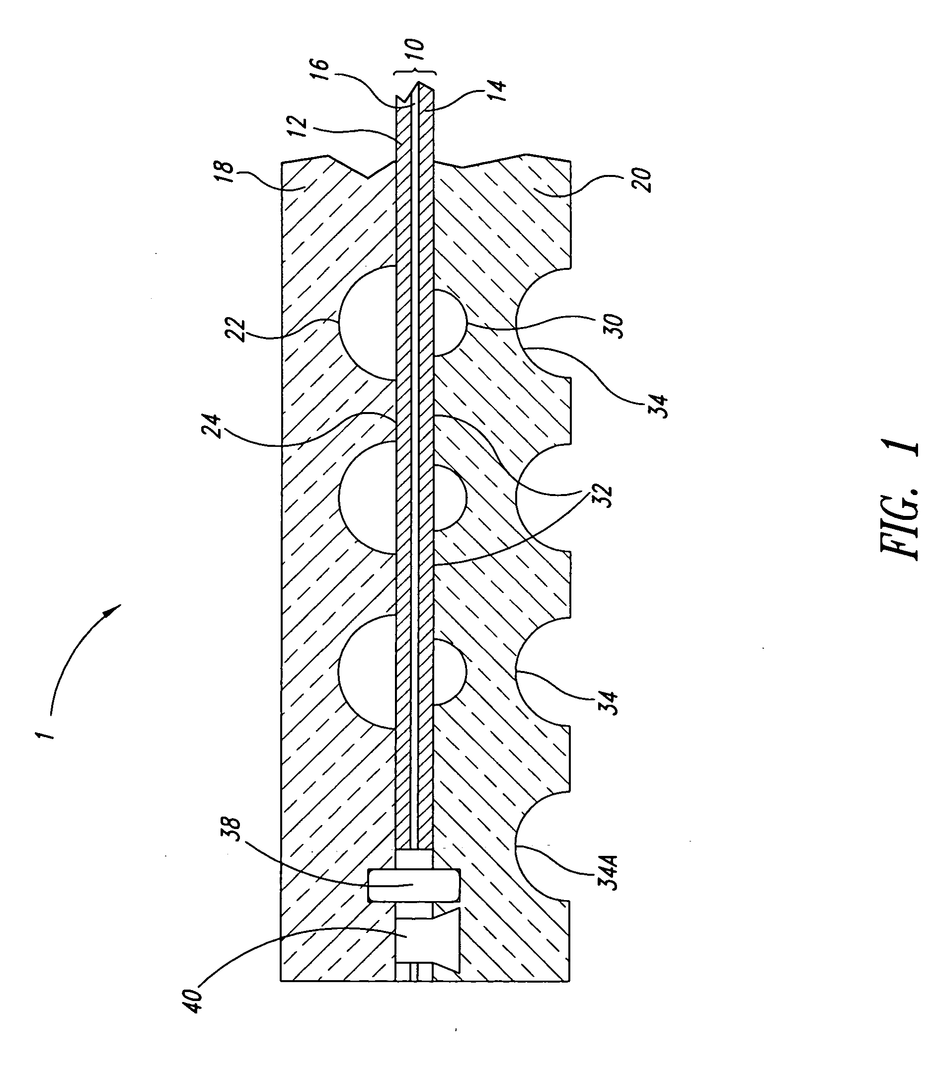
[0024]FIG. 1 is a partial cross-sectional view of a fuel cell assembly comprising an integrated voltage reversal protection diode. Cell 10 comprises a cathode 12, an anode 14, and an electrolyte 16 interposed therebetween. Cell 10 is interposed between oxidant flow field plate 18 and fuel flow field plate 20 to form fuel cell assembly 1. Oxidant channels 22, separated by land areas 24, are formed in the surface of oxidant flow field plate 18 which faces cell 10. Similarly, fuel channels 30, separated by land areas 32, are formed in the surface of fuel flow field plate 20 which faces cell 10.

[0025] In a more specific embodiment, fuel cell assembly 1 is a solid polymer electrolyte fuel cell assembly, cell 10 is a membrane electrode assembly (MEA) and electrolyte 16 is a solid polymer electrolyte or ion-exchange membrane.

[0026] As shown in FIG. 1, perimeter seal 38 circumscribes cell 10 and is interposed between the pair of flow field plates, namely, oxidant flow field plate 18 and f...


PUM

PropertyMeasurementUnit
output voltageaaaaaaaaaa
threshold voltageaaaaaaaaaa

Abstract

An electrochemical fuel cell stack comprises a plurality of fuel cell assemblies, wherein, each fuel cell assembly comprises a cell compressed between a pair of flow field plates, a perimeter seal circumscribing the cell and interposed between the pair of flow field plates, and a first diode, having an aspect ratio greater than 10:1, positioned adjacent to, and outside of, the perimeter seal along a first edge of the cell and interposed between the pair of flow field plates.

Description

BACKGROUND OF THE INVENTION [0001] 1. Field of the Invention [0002] This invention relates generally to electrochemical fuel cell stacks. More specifically, the present invention relates to electrochemical fuel cell stacks comprising a plurality of fuel cell assemblies having integrated diodes. [0003] 2. Description of the Related Art [0004] Fuel cell systems are currently being developed for use as power supplies in a wide variety of applications, such as automobiles and stationary power plants. Such systems offer the promise of delivering power economically while providing environmental and other benefits. To be commercially viable, however, fuel cell systems should exhibit adequate reliability in operation, even when the fuel cells are subjected to conditions outside their preferred operating ranges. [0005] Fuel cells convert reactants, namely, fuel and oxidant, to generate electric power and reaction products. Fuel cells generally employ an electrolyte disposed between two elect...

Claims


Application Information

Patent Timeline
Patent Type & Authority Applications(United States)
IPC IPC(8): H01M2/08H01M8/02H01M8/04H01M8/10H01M8/24
CPCH01M8/0271H01M8/04552Y02E60/50H01M8/04955H01M8/241H01M8/04671H01M8/0263H01M8/0267H01M8/2483H01M8/242
Inventor KNIGHTS, SHANNA D.DE VAAL, JACOB W.LAURITZEN, MICHAEL V.WILKINSON, DAVID P.
Owner BDF IP HLDG
Why Eureka
Try Eureka