Fuel cell system and method for discharging reaction gas from fuel cell

a fuel cell and reaction gas technology, applied in the direction of fuel cells, solid electrolyte fuel cells, electrical equipment, etc., can solve the problems of unstable power generation of the fuel cell, deterioration of power generation efficiency, and difficulty in controlling the concentration of diluted hydrogen, so as to improve the efficiency of electrical power generation, prevent the more excessive discharging of reaction gas containing impurities, and improve the effect of electrical power generation

Inactive Publication Date: 2005-06-16
HONDA MOTOR CO LTD
View PDF1 Cites 11 Cited by
  • Summary
  • Abstract
  • Description
  • Claims
  • Application Information

AI Technical Summary

Benefits of technology

[0013] Accordingly, the present invention provides a fuel cell system which can properly set the operation timing of a discharge valve when the system includes a plurality of determining units.
[0015] In this configuration, the discharge valve is prevented from being opened even if one valve open control unit instructs a valve to open until a predetermined time period has elapsed since discharge valve was opened in response to a valve open command issued by another valve open control unit. Thus, reaction gas containing impurities is prevented from being discharged excessively.
[0029] According to the first aspect of the present invention, the efficiency of electrical power generation can be improved since excessive discharging of reaction gas containing impurities can be prevented.
[0030] According to the second aspect of the present invention, excessive discharging of reaction gas containing impurities can be prevented more properly since a valve open interval of a discharge valve can be changed according to the operating status of the fuel cell.

Problems solved by technology

Impurities at the anode side, such as water or nitrogen and the like, may make power generation of the fuel cell unstable.
Such a successive opening of a discharge valve would result in excessive discharging of hydrogen gas together with impurities, and the efficiency of power generation would deteriorate because it appears that the hydrogen consumption increases.
In addition, in a fuel cell having a dilution device which dilutes hydrogen gas discharged from a hydrogen circulation path with a cathode off-gas which is the gas discharged from the cathode, it is difficult to control the concentration of the diluted hydrogen.
Such a successive or simultaneous opening of multiple discharge valves would cause excessive discharging of hydrogen gas together with impurities, and the efficiency of power generation deteriorate because it appears that the hydrogen consumption increases.
In addition, in a fuel cell having a dilution device which dilutes hydrogen gas discharged from a hydrogen circulation path with a cathode off-gas which is the gas discharged from the cathode, it is difficult to control the concentration of the diluted hydrogen.

Method used


Image

  • Fuel cell system and method for discharging reaction gas from fuel cell
  • Fuel cell system and method for discharging reaction gas from fuel cell
  • Fuel cell system and method for discharging reaction gas from fuel cell

Examples


first embodiment

[0050] First, a first embodiment of a fuel cell system according to the present invention will be explained with reference to FIGS. 1 to 3.

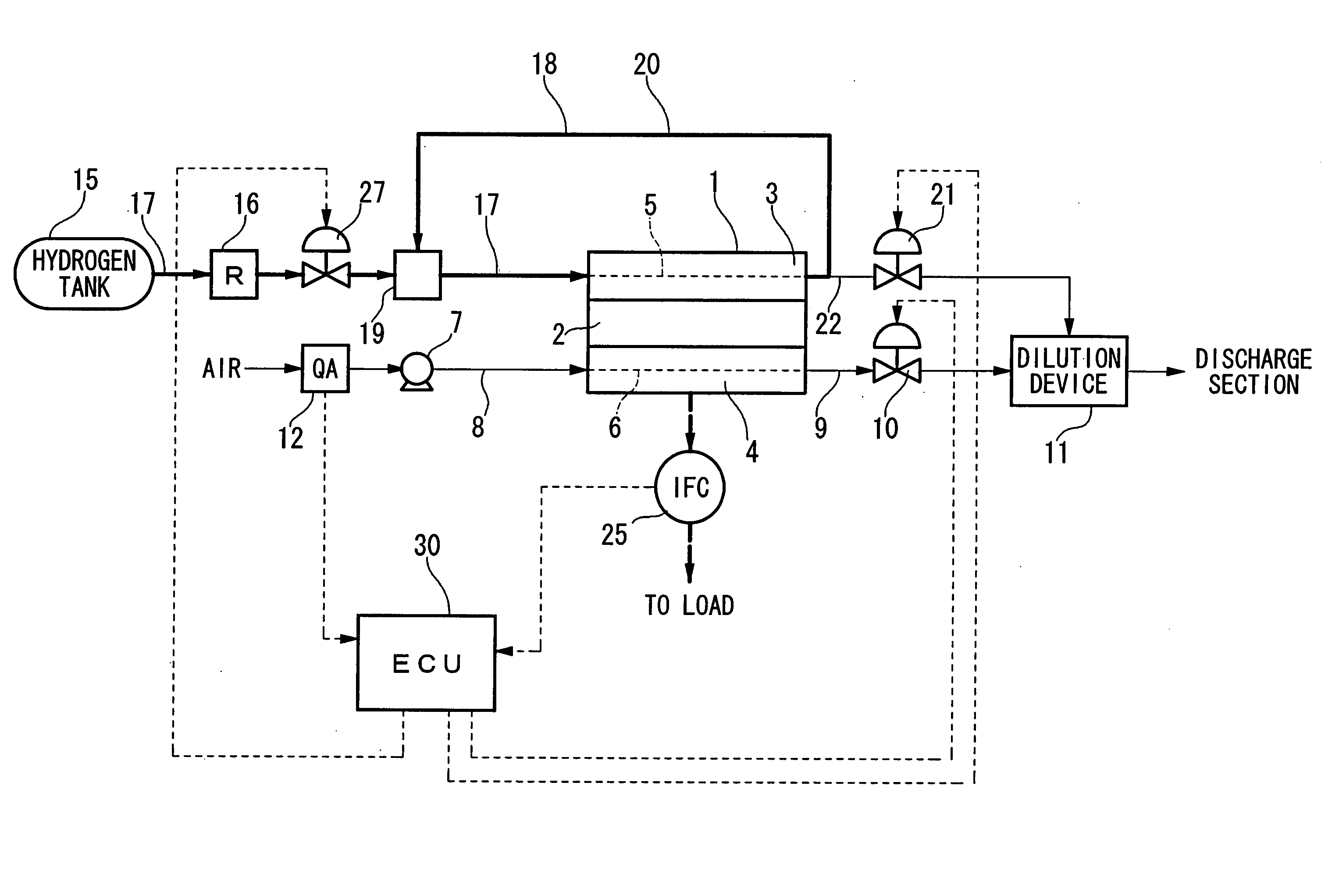
[0051]FIG. 1 is schematic diagram illustrating a fuel cell system having the fuel cell system according to the present invention, and this fuel cell is mounted on a fuel cell vehicle in this example.

[0052] A fuel cell 1 generates electrical power from a chemical reaction of reaction gases, and the fuel cell 1 includes a plurality of cells, and each cell includes, for example, a solid polymer electrolyte membrane 2 made of solid polymer ion-exchange membrane and the like sandwiched between an anode 3 and a cathode 4 (in FIG. 1, only one cell is shown). When hydrogen gas (reaction gas) is supplied to a reaction gas communication path 5 of the anode 3 as a fuel gas, and air containing oxygen (reaction gas) is supplied to a reaction gas communication path 6 of the cathode 4 as an oxidizer gas; hydrogen ion generated by a catalytic reaction in the a...

second embodiment

[0074] Next, the fuel cell system according to a second embodiment of the present invention will be explained with reference to FIGS. 5 to 7.

[0075] The major difference in the discharge systems for a fuel cell between the first and the second embodiment is that the discharge systems of the second embodiment includes two discharge valves for discharging anode off-gas.

[0076] More specifically, as shown in FIG. 5, an anode off-gas discharge path (discharge path) 22 including the first discharge valve 21A is branched from the anode off-gas path 18 and is connected to the dilution device 11. Furthermore, an anode off-gas discharge path 24 including the second discharge valve 21B is branched from a portion of the anode off-gas discharge path 22 located upstream from the first discharge valve 21A, and the anode off-gas discharge path 24 is also connected to the dilution device 11. In the dilution device 11, anode off-gas discharged from the anode off-gas discharge paths 22 and 24 is dilu...

third embodiment

[0094] Next, the fuel cell system according to a third embodiment of the present invention will be explained with reference to FIGS. 9 to 11. Since the configuration of the discharge system in the third embodiment is the same as that in the first embodiment shown in FIG. 1, the discussion of the third embodiment is omitted.

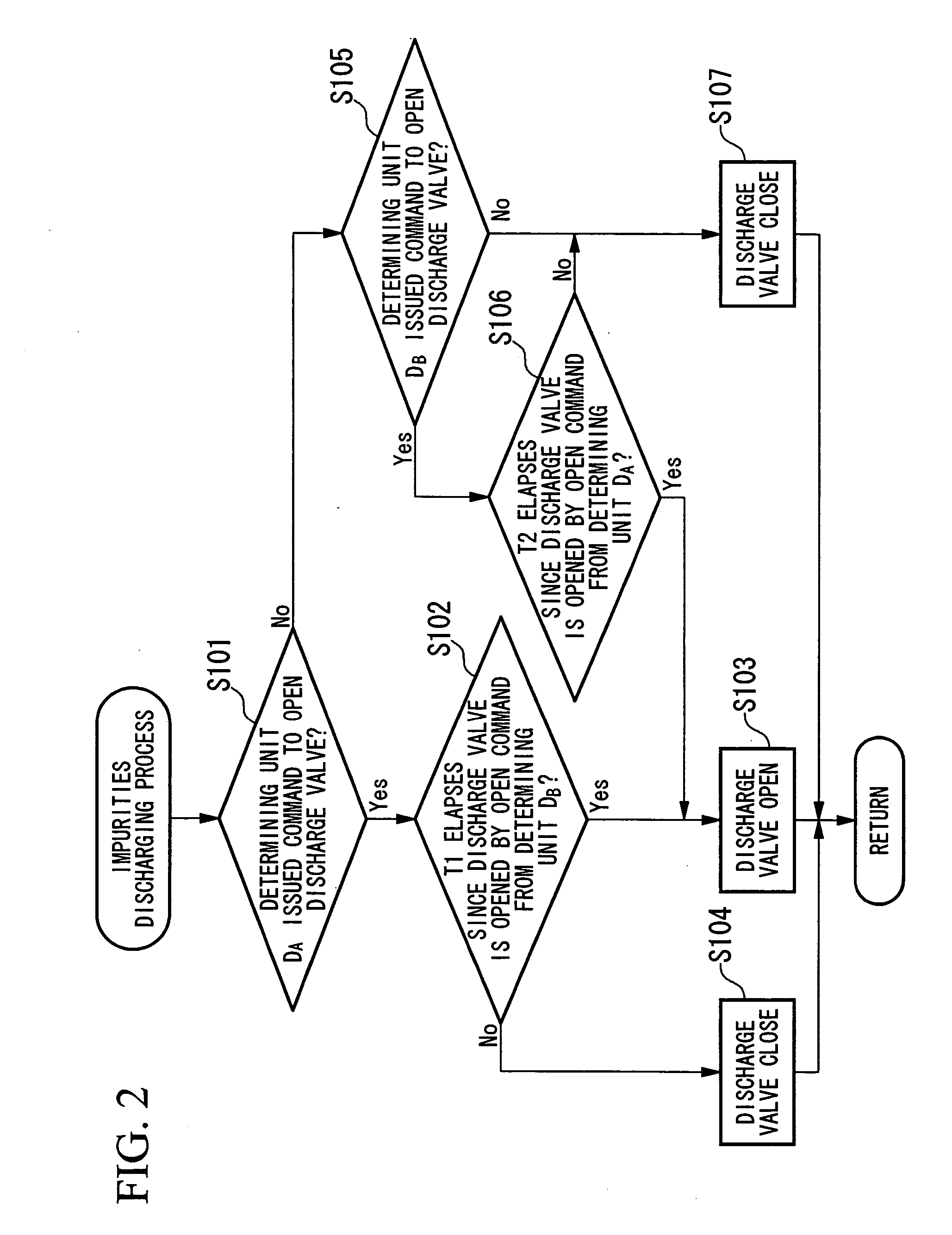
[0095] The fuel cell system of the third embodiment differs from the first embodiment in that the determining unit used for the decision on whether or not discharge of impurities has is selected between the determining unit DA and the determining unit DB, and the selection is made according to a preset condition which indicates the operating status of the fuel cell 1.

[0096] More specifically, in the third embodiment, two determining units are selected based on modes indicating the operating status of the fuel cell 1: Modes A and B. Mode A indicates that power generation by the fuel cell 1 is stable, and Mode B indicates the situation other than Mode A. In Mode A...


PUM

PropertyMeasurementUnit
DAaaaaaaaaaa
electrical poweraaaaaaaaaa
time periodaaaaaaaaaa

Abstract

A fuel cell system includes: a fuel cell which generates electrical power from a chemical reaction of a reaction gas; a discharge path for discharging the reaction gas supplied to the fuel cell; a discharge valve which is provided in the discharge path and discharges the reaction gas from the discharge path; and valve control units for controlling opening of the discharge valve, wherein the valve control units are adapted such that, since the discharge valve has been opened by a valve open command issued by one of the valve control units, the valve control units prohibit the discharge valve from being opened by a valve open command issued by any of the other valve control units until a predetermined time period elapses.

Description

BACKGROUND OF THE INVENTION [0001] 1. Field of the Invention [0002] The present invention relates to a fuel cell system. [0003] Priority is claimed on Japanese Patent Application No. 2003-386570, filed Nov. 17, 2003, the content of which is incorporated herein by reference. [0004] 2. Description of Related Art [0005] One type of fuel cell is a fuel cell installed in a fuel cell vehicle and the like, and such a fuel cell generates electrical power by a chemical reaction of reaction gas. This type of fuel cell, for example, includes a fuel cell in which a solid polymer electrolyte membrane is sandwiched between an anode and a cathode. A fuel gas (e.g., hydrogen gas) is supplied to the anode, and an oxidizer gas (e.g., air containing oxygen) is supplied to the cathode, and chemical energy involved in the reduction in these reaction gases is extracted as electric energy. [0006] In such a fuel cell, water is generated at the cathode side during the power generation, and a part of the gen...

Claims


Application Information

Patent Timeline
Patent Type & Authority Applications(United States)
IPC IPC(8): H01M8/04H01M8/10
CPCH01M8/04089H01M8/04097H01M8/04231Y02E60/50H01M8/04589H01M8/04761H01M8/04992H01M8/04552
Inventor OJIMA, KUNIAKIYOSHIKAWA, SHINJIMATSUMOTO, YUJIUEHARA, JUNJIUEDA, KENICHIRO
Owner HONDA MOTOR CO LTD
Why Eureka
Try Eureka