
Method for identifying basic blocks with conditional delay slot instructions

a conditional delay and instruction technology, applied in the field of processing, can solve the problems of complex canceling of speculative instructions, affecting the design of processors, and presenting numerous challenges to processor designers

Inactive Publication Date: 2005-06-16
AVAGO TECH INT SALES PTE LTD
View PDF4 Cites 2 Cited by
  • Summary
  • Abstract
  • Description
  • Claims
  • Application Information

AI Technical Summary

Benefits of technology

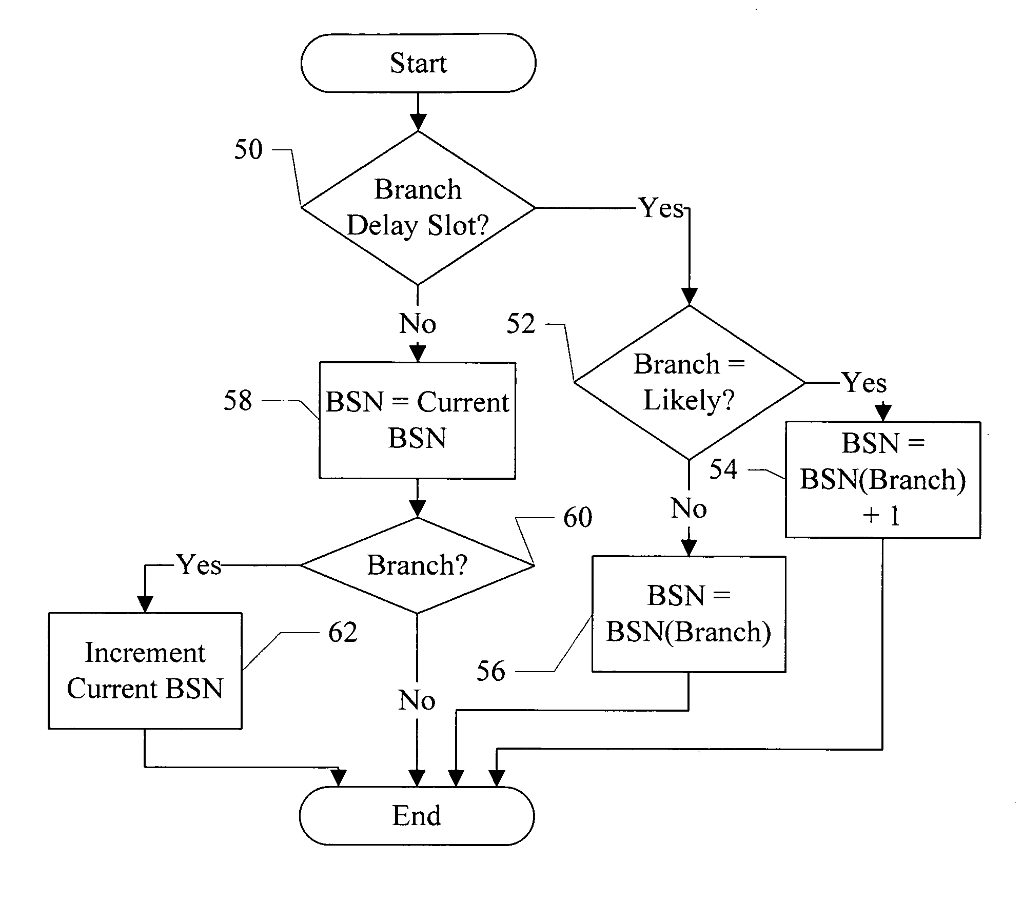
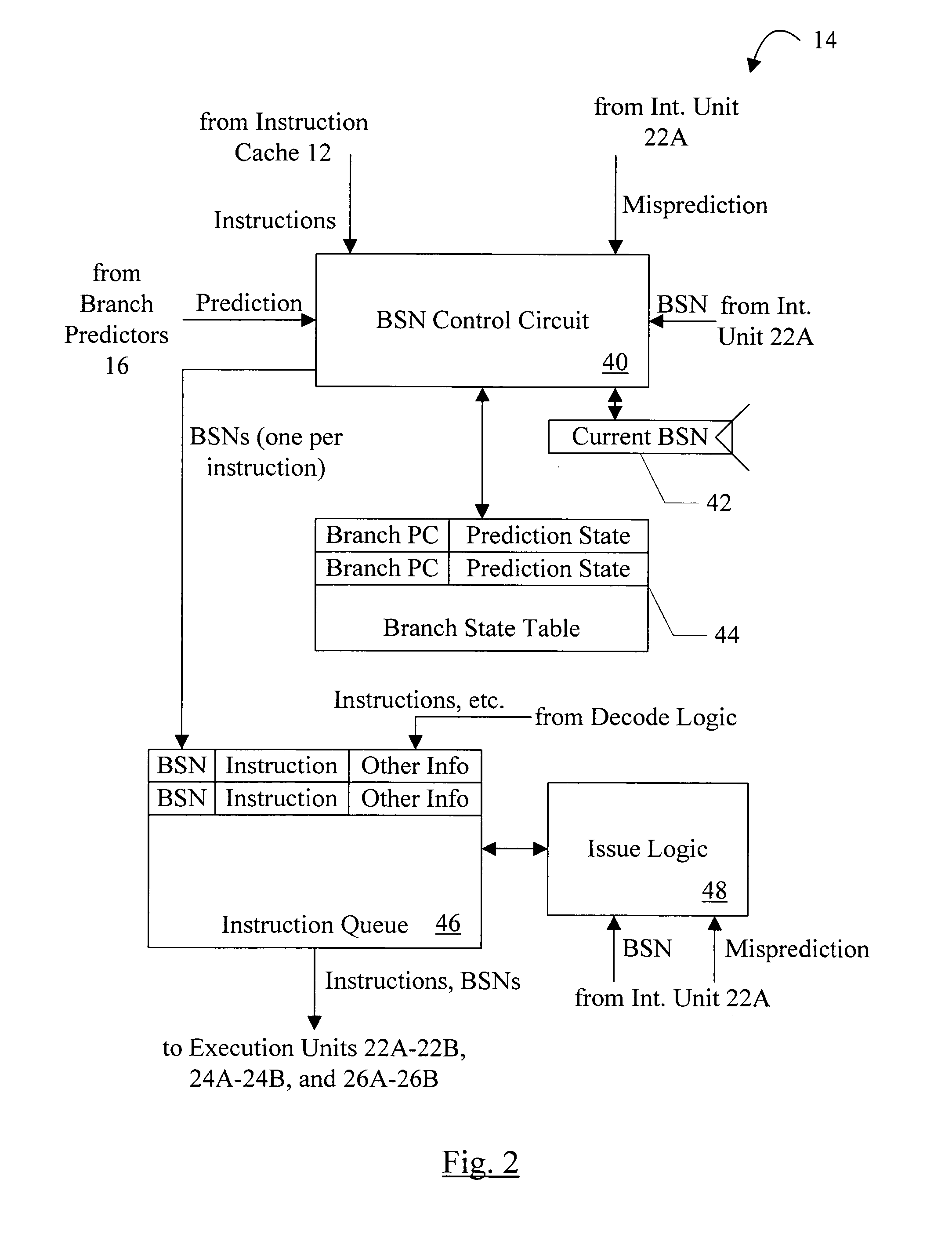
The patent describes a mechanism for handling instruction cancellation for mispredicted branch instructions. It assigns a tag to a branch instruction and a tag to an instruction in the branch delay slot. If the branch is mispredicted, the first tag is broadcast to pipeline stages that may have speculative instructions, and the first tag is compared to tags in the pipeline stages. If the tag matches, the instruction is not cancelled. If the tag mismatches, the instruction is cancelled. This mechanism ensures that the proper cancellation or non-cancellation of the branch delay slot instruction. In one embodiment, the assignment of tags for a fetch group of concurrently fetched instructions may be performed in parallel.

Problems solved by technology

Branch instructions present numerous challenges to processor designers.
However, if the prediction is incorrect, the speculative instructions must be cancelled.
Canceling the speculative instructions, particularly in wide issue processors, may be complex.
A further difficulty introduced in some instruction set architectures (e.g. the MIPS instruction set architecture) involves the branch delay slot.
Any type of instruction may be in the branch delay slot, and thus locating the instruction and canceling or not canceling the instruction based on which branch instruction that instruction follows is complicated.

Method used


Image

  • Method for identifying basic blocks with conditional delay slot instructions
  • Method for identifying basic blocks with conditional delay slot instructions
  • Method for identifying basic blocks with conditional delay slot instructions

Examples


Embodiment Construction

[0023] Processor Overview

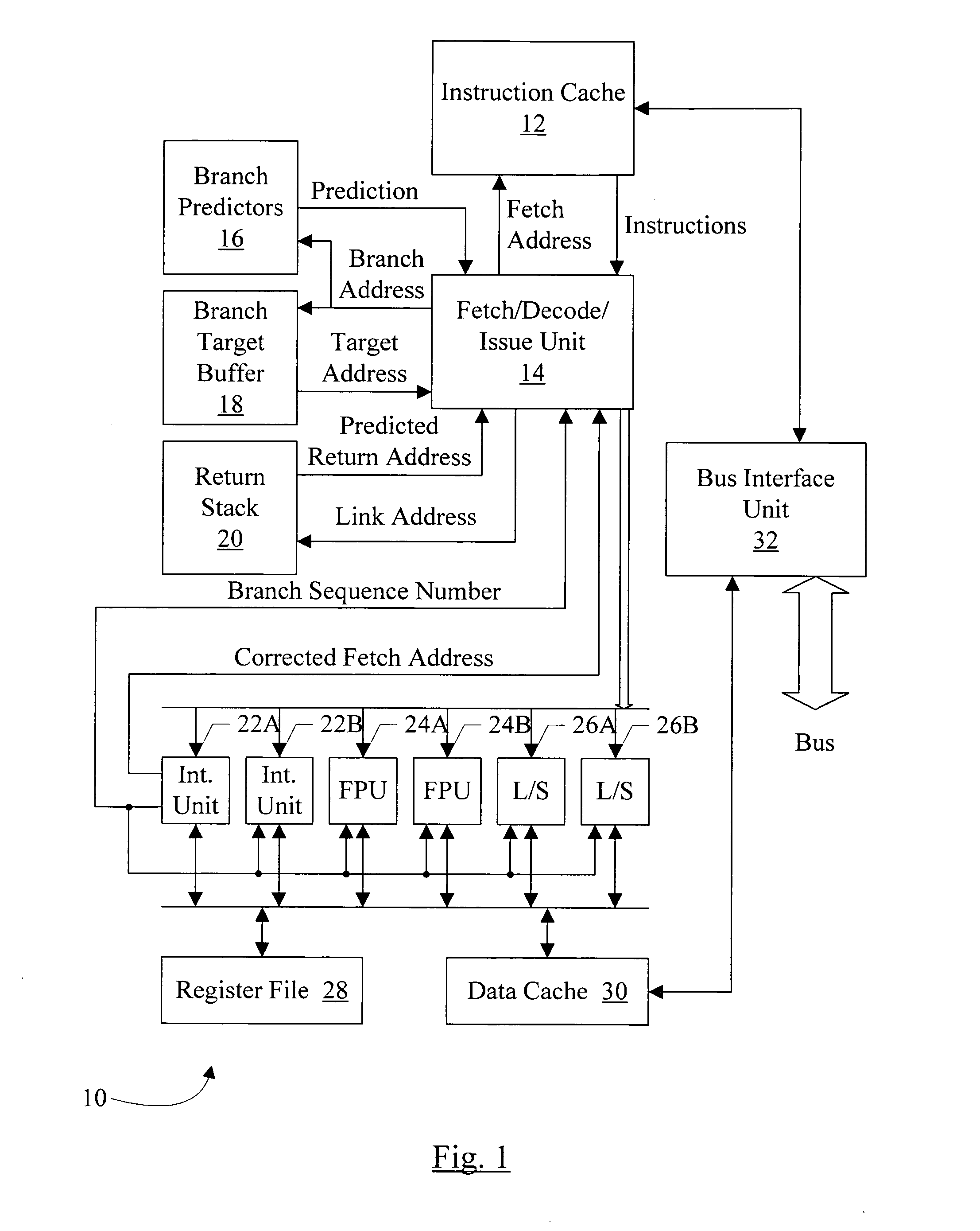
[0024] Turning now to FIG. 1, a block diagram of one embodiment of a processor 10 is shown. Other embodiments are possible and contemplated. In the embodiment of FIG. 1, the processor 10 includes an instruction cache 12, a fetch / decode / issue unit 14, a branch predictors unit 16, a branch target buffer 18, a return stack 20, a set of integer execution units 22A-22B, a set of floating point execution units 24A-24B, a set of load / store execution units 26A-26B, a register file 28, a data cache 30, and a bus interface unit 32. The instruction cache 12 is coupled to the bus interface unit 32, and is coupled to receive a fetch address from, and provide corresponding instructions to, the fetch / decode / issue unit 14. The fetch / decode / issue unit 14 is further coupled to the branch predictors 16, the branch target buffer 18, the return stack 20, and the execution units 22A-22B, 24A-24B, and 26A-26B. Specifically, the fetch / decode / issue unit 14 is coupled to provide a b...


PUM


Abstract

A first tag is assigned to a branch instruction. Dependent on the type of branch instruction, a second tag is assigned to an instruction in the branch delay slot of the branch instruction. If the branch is mispredicted, the first tag is broadcast to pipeline stages that may have speculative instructions, and the first tag is compared to tags in the pipeline stages to determine which instructions to cancel. The assignment of tags for a fetch group of concurrently fetched instructions may be performed in parallel. A plurality of branch sequence numbers may be generated, and one of the plurality may be selected for each instruction responsive to the cumulative number of branch instructions preceding that instruction within the fetch group. The selection may be further responsive to whether or not the instruction is in a conditional delay slot.

Description

PRIORITY INFORMATION [0001] This application is a continuation of and claims priority to U.S. Patent Application having an application Ser. No. 09 / 961,579; filed Sep. 24, 2001, which application is hereby incorporated by reference.BACKGROUND OF THE INVENTION [0002] 1. Field of the Invention [0003] This invention is related to the field of processors and, more particularly, to the canceling of speculative instructions in response to a branch misprediction. [0004] 2. Description of the Related Art [0005] Branch instructions present numerous challenges to processor designers. The existence of branch instructions in code, and the mechanisms that the processor includes to handle the branch instructions with high performance, are frequently large factors in determining the overall performance that a user may actually experience when using a system including the processor. [0006] One mechanism frequently used to address the challenges presented by branch instructions is speculative operati...

Claims


Application Information

Patent Timeline
Patent Type & Authority Applications(United States)
IPC IPC(8): G06F9/38
CPCG06F9/3842
Inventor KRUCKEMYER, DAVID A.
Owner AVAGO TECH INT SALES PTE LTD
Learn More