Toilet overflow prevention device

a toilet and overflow technology, applied in the field of toilet systems, can solve the problems of preferably requiring a low level of installation skill, and achieve the effect of low installation skill and cost-effectiveness

Active Publication Date: 2005-06-23
LIMIT
View PDF13 Cites 4 Cited by
  • Summary
  • Abstract
  • Description
  • Claims
  • Application Information

AI Technical Summary

Benefits of technology

[0007] Preferred embodiments of the present invention operate to prevent toilet overflow in a cost-effective and reliable manner. In addition, preferred embodiments may be integrated into a toilet assembly during manufacture or retrofitted into an existing toilet, preferably with little or no modification of the standard toilet. Embodiments intended for retrofitting in existing toilets preferably require a low level of skill to install.

Problems solved by technology

Embodiments intended for retrofitting in existing toilets preferably require a low level of skill to install.

Method used


Image

  • Toilet overflow prevention device
  • Toilet overflow prevention device
  • Toilet overflow prevention device

Examples


Embodiment Construction

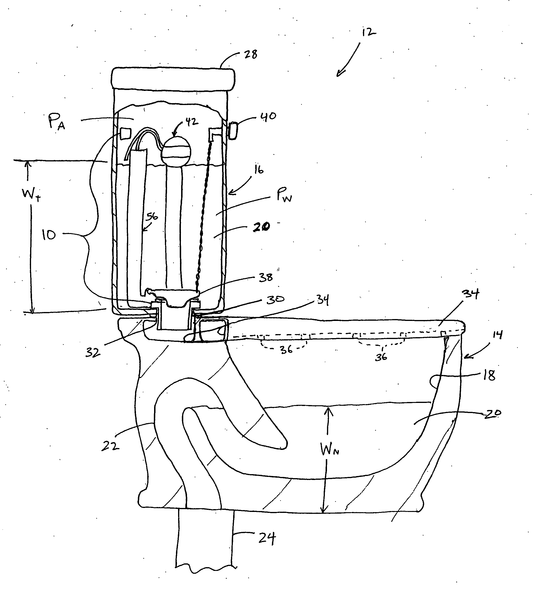
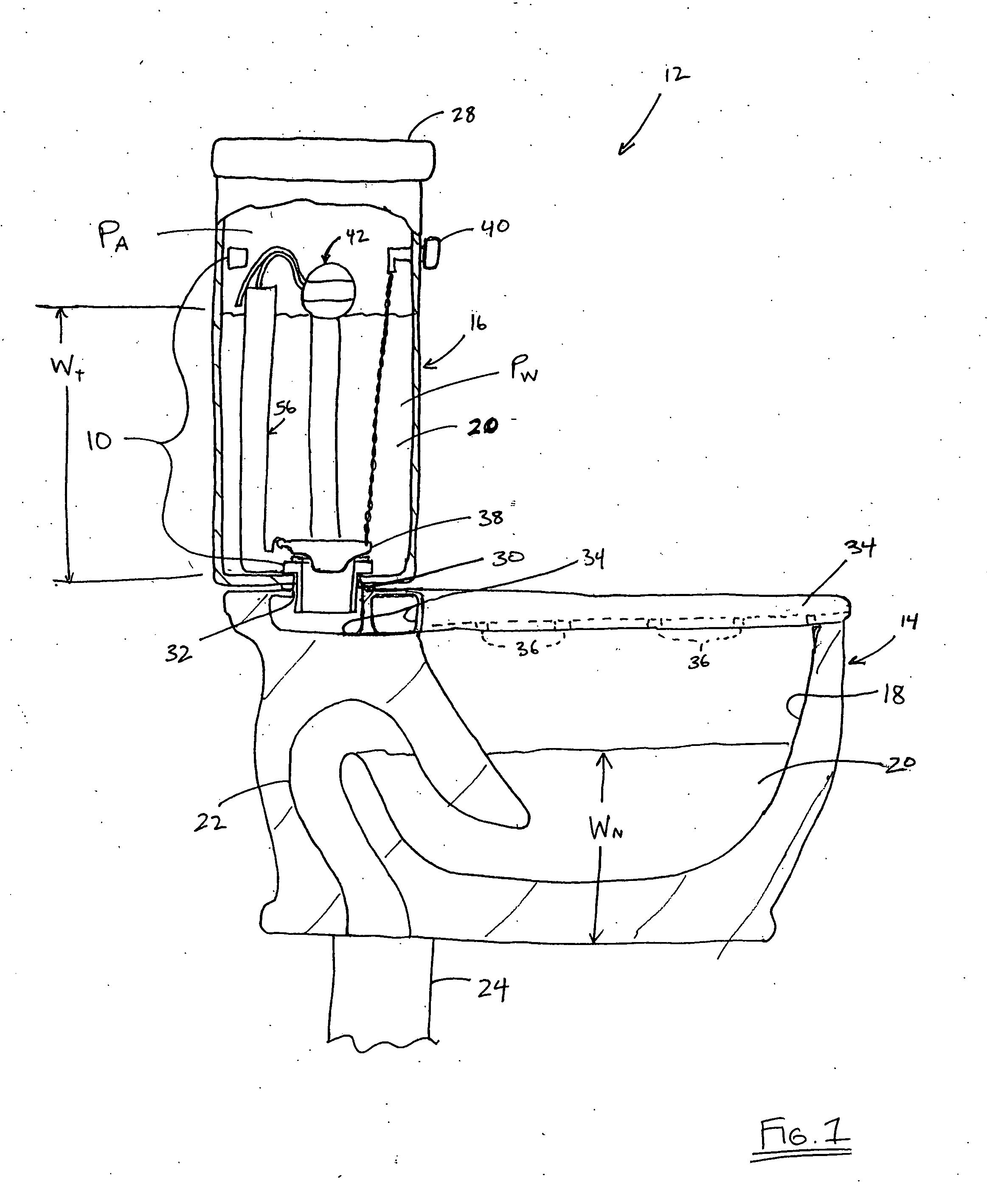
[0021]FIG. 1 illustrates a preferred embodiment of the toilet overflow prevention device 10 incorporated within a toilet 12. The toilet 12 preferably is of a conventional configuration and includes a base 14 and a tank 16 supported on the base 14. Although the overflow prevention device 10 is described herein in the context of such a toilet 12 having a base 14 and a tank 16, the device 10 may be adapted for use with toilets having alternative configurations, as will be appreciated by one of skill in the art in view of the present disclosure.

[0022] The base 14 defines a bowl 18, which is configured to hold a volume of water 20. A siphon tube 22 connects the bowl 18 with a wastewater plumbing system 24. The siphon tube 22 extends in an upward direction from a lower portion of the bowl 18 and then curves into a downward direction toward the lower end of the base 14 to meet the wastewater plumbing system 24. Accordingly, the height of the upper curve 14a determines a normal water level...


PUM


Abstract

A toilet overflow prevention device including an overflow valve assembly, a control valve and a water level sensor. The overflow valve assembly is configured to selectively permit a flow of water through the valve assembly from the tank to the bowl of an associated toilet. The water level sensor is configured to provide a control signal in response to detecting an above-normal water level within the bowl of the toilet. The control valve is configured to actuate the overflow valve assembly in response to a control signal from the water level sensor. Preferably, the overflow valve assembly is separate from the primary flush valve of the toilet and is located between the primary flush valve and the bowl of the toilet.

Description

BACKGROUND OF THE INVENTION [0001] 1. Field of the Invention [0002] The present invention relates generally to toilet systems and, more particularly, to overflow prevention devices for toilets. [0003] 2. Description of the Related Art [0004] Although significant advances have been made in toilet technology, particularly in reducing the amount of water needed for flushing purposes, a satisfactory solution for preventing the overflow of a toilet in the event of a blockage of the toilet bowl, or associated waste plumbing, has not been achieved. [0005] Prior art overflow prevention arrangements have tended to be complex and often require a customized toilet design or significant modification of a standard toilet. For example, as disclosed in U.S. Pat. No. 6,052,841, one prior art solution utilizes a water level sensor and an electric motor to close a valve thereby preventing a flow of water from the toilet tank to the bowl in response to an above-normal water level. Such an arrangement ...

Claims


Application Information

Patent Timeline
Patent Type & Authority Applications(United States)
IPC IPC(8): E03D1/00E03D11/00
CPCE03D11/00E03D1/00Y10T137/7329Y10T137/7371Y02A10/30
Inventor BUTSCH, OTTO R.BOWCUTT, KEVIN G.BLAKE, GREGORYCORBIN, DANIEL L.REPP, DENNIS A.
Owner LIMIT
Why Eureka
Try Eureka