Internal combustion engine valve seating velocity control

a technology of internal combustion engine and seat, which is applied in the direction of non-mechanical valves, valve arrangements, machines/engines, etc., can solve the problems of excessive valve seating impact velocity, valve itself, and compromising the sealing ability of the valve, and achieve the effect of reducing the impact velocity of the valve sea

Inactive Publication Date: 2005-06-23
CATERPILLAR INC
View PDF9 Cites 19 Cited by
  • Summary
  • Abstract
  • Description
  • Claims
  • Application Information

AI Technical Summary

Benefits of technology

[0012] In yet another aspect, the present disclosure provides a method of reducing valve seating impact velocity. The method includes the steps of operably coupling a valve to a hydraulic actuator that includes a plunger, and moving the valve toward its seat at least in part by expelling fluid through an unrestricted passage in a body. The method further includes the step of slowing the valve as it approaches its seat at least in part by expelling the fluid through a restricted passage disposed in at least one of the body and the plunger.

Problems solved by technology

Excessive valve seating impact velocity is a problem familiar to many hydraulic system designers.
When a valve impacts its seat at too high a velocity, the seat and / or the valve itself can be damaged, compromising the sealing ability of the valve and in some instances rendering the valve inoperable.
Repeated impacts of the valve against its seat can deform, break or otherwise damage the components, causing gases to leak past the valve seat when closed or worse, breaking the valve altogether.
However, the small, rapidly moving hydraulic parts from some known systems must often be machined to very close tolerances, making mass production challenging and expensive.
Moreover, during cold start conditions it can be difficult to initiate operation of a hydraulic system having numerous small parts bathed in cold, viscous oil.
In particular, Weber requires a relatively large number of parts for its snubber assembly.

Method used


Image

  • Internal combustion engine valve seating velocity control
  • Internal combustion engine valve seating velocity control
  • Internal combustion engine valve seating velocity control

Examples


Embodiment Construction

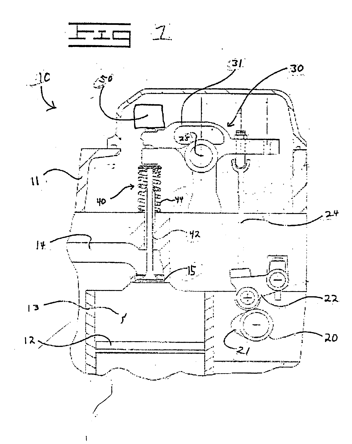
[0017] Referring to FIG. 1, there is shown an engine 10 in accordance with a preferred embodiment of the present disclosure. Engine 10 includes an engine housing 11 defining a cylinder 13 within which a piston 12 is reciprocable. Engine 10 may be any internal combustion engine; it is contemplated that in a preferred embodiment engine 10 will be a compression ignition engine such as a conventional diesel engine, and may be operable as a homogeneous charge compression ignition diesel engine. Engine 10 further provides a gas exchange valve assembly 40 having a gas exchange valve member 42 that reciprocates between an open position and a closed position, as depicted in FIG. 1, the valve member being biased toward its closed position with a return spring 44. A gas exchange passage 14 is further defined by engine housing 11, and may be either of an exhaust passage for expelling combustion products, or an intake passage supplying air for combustion with fuel.

[0018] In a preferred embodime...


PUM


Abstract

The present disclosure provides an engine having a gas exchange valve and an actuator for the gas exchange valve, and also a method of reducing valve seating impact velocity. The actuator includes a body having a fluid inlet and a fluid outlet. A plunger is reciprocable in the body and has a travel distance between an advanced position and a retracted position, the plunger and body defining a chamber. A flow restriction orifice is disposed in at least one of the plunger and the body, and the chamber is in unrestricted fluid communication with the outlet over a first portion of the travel distance and in restricted fluid communication with the outlet by way of the orifice over at least a second portion of the travel distance.

Description

CROSS-REFERENCE TO RELATED APPLICATION [0001] This Application is a Continuation-in-Part of U.S. patent application Ser. No. 10 / 743,000, filed Dec. 23, 2003, and entitled Engine Valve Actuation System.TECHNICAL FIELD [0002] The present disclosure relates generally to internal combustion engine valve assemblies, and more particularly to a snubber for controlling seating impact velocity of a gas exchange valve in an internal combustion engine. BACKGROUND [0003] Excessive valve seating impact velocity is a problem familiar to many hydraulic system designers. In many modern applications, high speed hydraulic valves and related components may reciprocate many times per second. [0004] In order to generate such rapid action, the system components are often driven with relatively high forces. When a valve impacts its seat at too high a velocity, the seat and / or the valve itself can be damaged, compromising the sealing ability of the valve and in some instances rendering the valve inoperable...

Claims


Application Information

Patent Timeline
Patent Type & Authority Applications(United States)
IPC IPC(8): F01L9/10F01L1/34
CPCF01L9/02F01L1/146F01L1/181F01L13/0015F01L2001/054F01L2305/00F01L9/10
Inventor CHANG, DAVID YU-ZHANG
Owner CATERPILLAR INC
Why Eureka
Try Eureka