[0026] In many of the preferred embodiments, fluids are mixed in a zone that does not contain any catalyst. There are several strong advantages for mixing inside of microchannels, and away from a microchannel heterogeneous catalyst zone, including the following: safe mixing of reactants within the flammability regime before the reaction zone; mixing of a diluent after the reaction section to quench a reaction or to move the mixture composition outside of the flammability region before entering macro connections; avoiding damage to a solid catalyst; or avoiding unwanted entrainment of solid catalyst.
[0027] A “diluent” is a nonreactive fluid, inhibitor, or a safening agent (for example, an agent that reduces flammability of a mixture).
[0028] In the present invention, a “microchannel” is defined as a channel having at least one dimension of 2 millimeters or less, in some embodiments I millimeters or less, and in some embodiments, 0.1 to 1 millimeters. As is understood in the art, a microchannel is not merely an orifice. The length of a microchannel (that is, the direction of flow during normal operation) is not the shortest dimension of a microchannel. Both height and width of a microchannel are substantially perpendicular to the direction of flow of reactants through the reactor. Microchannels are also defined by the presence of at least one inlet that is distinct from at least one outlet—microchannels are not merely channels through zeolites or mesoporous materials. The height and / or width of a microchannel is preferably about 2 mm or less, and more preferably 1 mm or less. Preferably, the length of a microchannel is greater than 1 cm, in some embodiments in the range of about 1 to 50 cm. The sides of the microchannel are defined by a microchannel wall of walls. The choice of material for the walls depends on the intended use. These walls are preferably made of a hard material such as a ceramic, an iron based alloy such as steel, or monel. In some embodiments, the microchannel walls are comprised of a stainless steel or Inconel® which is durable and has good thermal conductivity. The microchannel devices can be made by known methods, and in some preferred embodiments are made by laminating interleaved plates (also known as “shims”), and in some preferred embodiments, shims designed for reaction channels are interleaved with shims designed for heat exchange.
[0029] In some preferred embodiments, the microchannel devices are microchannel reactors that include a plurality of microchannel reaction channels, preferably in thermal contact with a plurality of adjacent heat exchange microchannels. A plurality of microchannels may contain, for example, 2, 10, 100, 1000 or more channels. In preferred embodiments, the microchannels are arranged in parallel arrays of planar microchannels, for example, at least 3 arrays of planar microchannels. In some preferred embodiments, multiple microchannel inlets are connected to a common header and / or multiple microchannel outlets are connected to a common footer. During operation, the heat exchange microchannels (if present) contain flowing heating and / or cooling fluids. Non-limiting examples of this type of known reactor usable in the present invention include those of the microcomponent sheet architecture variety (for example, a laminate with microchannels) exemplified in U.S. Pat. Nos. 6,200,536 and 6,219,973 (both of which are hereby incorporated by reference). Performance advantages in the use of this type of architecture include their relatively large heat and mass transfer rates, and the substantial absence of any explosive limits. Microchannel reactors can combine the benefits of good heat and mass transfer, excellent control of temperature, residence time and minimization of by-products. Pressure drops can be low, allowing high throughput. Furthermore, use of microchannel reactors can achieve better temperature control, and maintain a relatively more isothermal profile, compared to conventional systems. In addition to the process microchannel(s), additional features such as microchannel or non-microchannel heat exchangers may be present. Microchannel heat exchangers are preferred. Heat exchange fluids may flow through adjacent heat transfer microchannels, and can be gases or liquids and may include steam, liquid metals, or any other known heat exchange fluids—the system can be optimized to have a phase change in the heat exchanger. In some preferred embodiments, multiple heat exchange layers are interleaved with multiple reaction microchannels (for example, at least 10 heat exchangers interleaved with at least 10 process microchannels. Microchannels are defined by microchannel walls that limit flow.
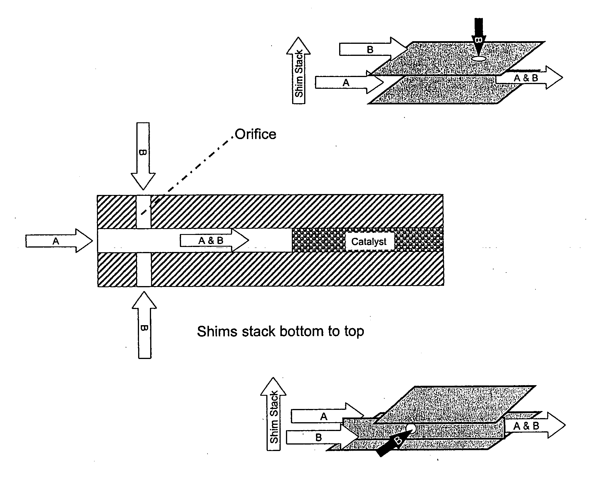
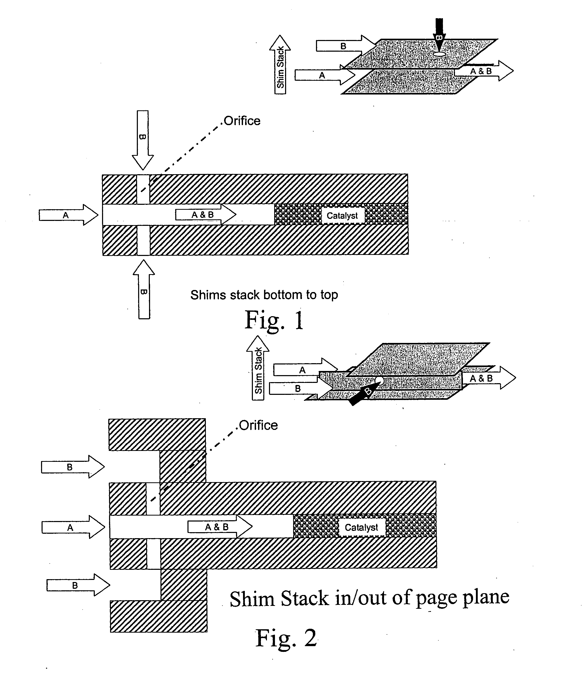
[0030] An “orifice” is a hole through a microchannel wall. Its length is the same as the thickness of the microchannel wall (unless it is slanted in which case its length will be slightly greater than this thickness. An “orifice” is not a T-joint or “Y” joint; in other words, two channels that flow together to form a single channel (in the shape of a “T” or a “Y”) are not an orifice. In general, the mixing lengths of a T or Y-joint are considerably longer than those created by orifices in the described invention. The lengths may be two times, five times, or even 10 times longer. The longer lengths create more time with a less well mixed feed stream; the results of more time with a lower mixing quality may be a lower selectivity to the desired product, a larger device, or increased safety concerns from a potentially flammable mixture.
[0031]“Opposing orifices” are orifices at opposite sides of a microchannel that may or may not be identical in size and geometry and are aligned such that flow through the opposing orifices collide with each other inside the microchannel.

