Vehicle anti-lock brake system and method

a technology of anti-lock brakes and brakes, which is applied in the direction of brake systems, braking components, transportation and packaging, etc., can solve the problems of not being equipped with sensing devices, the full system is complex and cost, and the cost of production and warehousing is higher

Inactive Publication Date: 2005-06-23
WABCO GMBH
View PDF1 Cites 3 Cited by
  • Summary
  • Abstract
  • Description
  • Claims
  • Application Information

AI Technical Summary

Benefits of technology

[0017] The present invention provides an improved ABS and an improved ABS ECU that is compatible with different types of ABSs to eliminate the need to maintain a large inventory of different ABS ECUs. Accordingly, the production, inventory, warehousing and other costs associated with maintaining multiple versions of ABS ECUs are avoided. The present invention also provides an improved ABS that avoids the above-described disadvantages associated with the installation of an incompatible ABS ECU.

Problems solved by technology

These wheels may or may not be equipped with sensing devices such as wheel speed sensors.
On the other hand, a disadvantage of this “full system” is its complexity and cost.
This translates into higher costs for production and warehousing, especially if only limited quantities of individual versions are sold.
Furthermore, if an ECU for a 6S / 4M ABS were to be mistakenly installed in a vehicle ABS equipped for a 6S / 6M ABS ECU, the 6S / 4M ABS ECU would recognize two superfluous modulators and signal an error if the 6S / 4M ABS ECU is properly connected to the 6S / 6M ABS via the associated cable harness.
However, if the plug connectors for the fifth and sixth modulators are not inserted in this case (the plug and socket connector between the cable harness and ABS ECU is the same for the two systems), the 6S / 4M ABS ECU would detect only four modulators and thus would erroneously recognize the installation to be valid and would deliver regulation signals (SL) unsuitable for regulated braking.

Method used


Image

  • Vehicle anti-lock brake system and method
  • Vehicle anti-lock brake system and method
  • Vehicle anti-lock brake system and method

Examples


Embodiment Construction

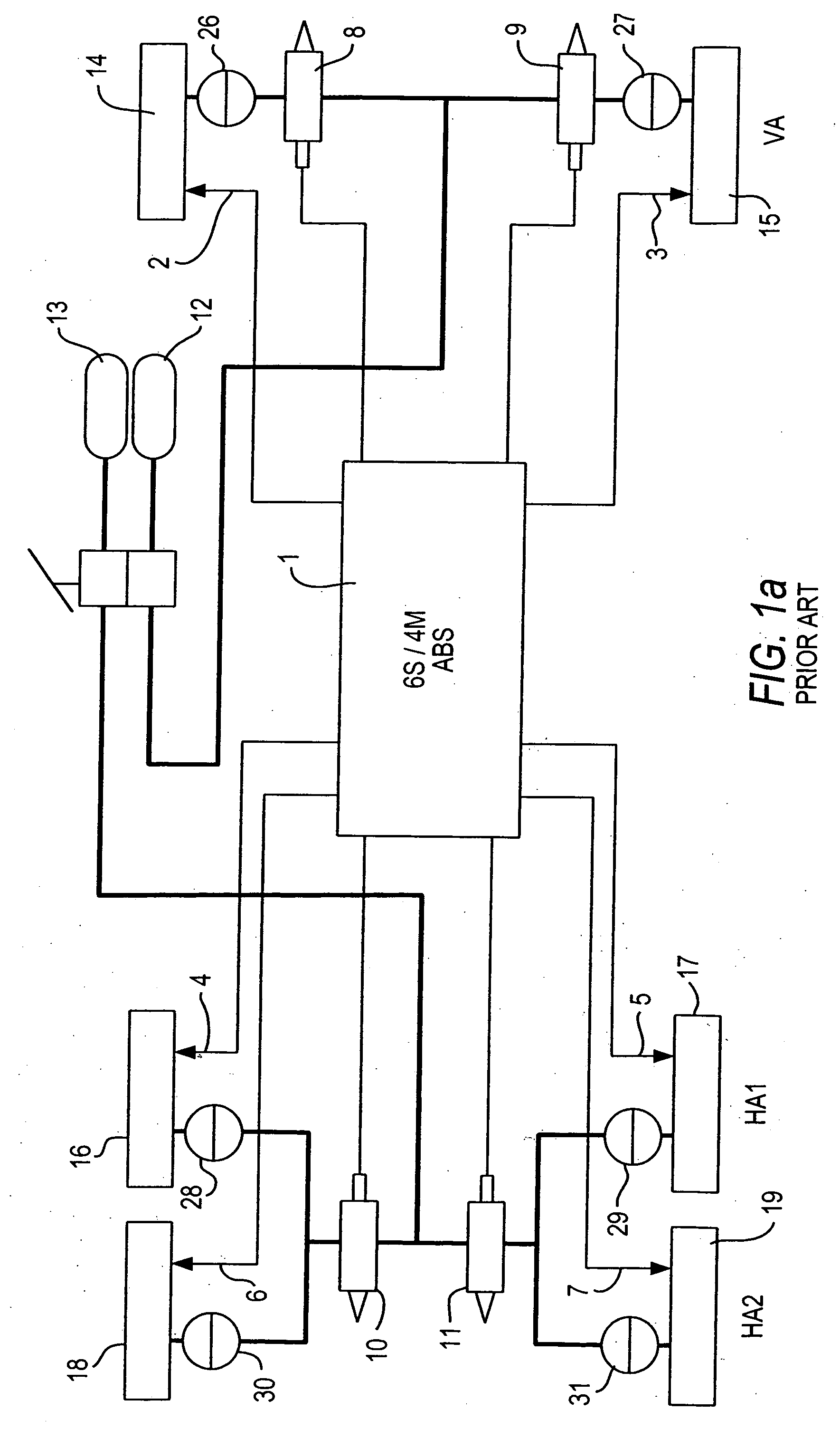
[0028] Referring now to the drawing figures where like reference numerals are used for corresponding parts, FIG. 1a shows, in a simplified, schematic diagram, a conventional 6S / 4M ABS (partial system) for a commercial tri-axle vehicle. The vehicle wheels 14 to 19 are associated with three axles, namely, a front axle VA, a first rear axle HA1 and a second rear axle HA2. The axles VA, HA1 and HA2 are preferably equipped with wheel speed sensors 2 to 7. The sensors 2 to 7 deliver speed signals to an ABS ECU 1.

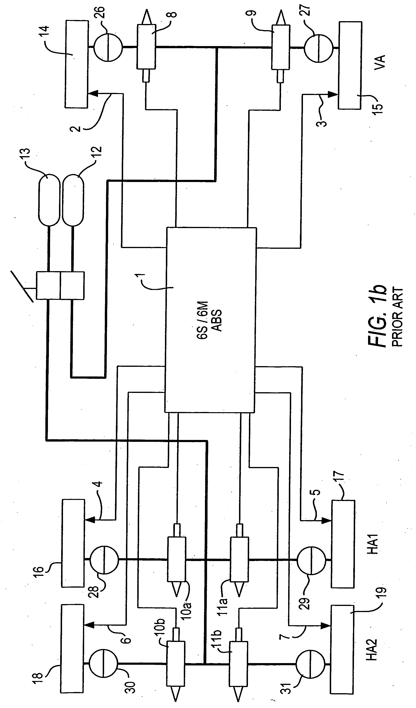
[0029] If the wheels 14 to 19 exhibit a tendency to lock, the ABS ECU 1 actuates brake pressure modulators 8 to 11 in known manner, so that brake pressure in brake cylinders 26 to 31 can be increased, maintained or reduced. The brake medium, such as, for example, compressed air, is preferably contained in reservoirs 12, 13. It should be understood that hydraulic fluid can also be used as the brake medium. Furthermore, brakes applied by electric motors can also be used. The workin...


PUM


Abstract

An anti-lock brake system for a tri-axle wheeled vehicle equipped with wheel speed sensors and modulators for adjusting brake pressure. The modulators are actuated by a six-channel electronic control unit. The modulators associated with the front axle of the vehicle are individually actuated. The modulators associated with the two rear axles of the vehicle are side-by-side or axle modulators, each actuated jointly by respective end stages of the six channels. The electronic control unit detects whether the anti-lock brake system in which it is installed is a compatible anti-lock brake system. An error signal indicating improper installation is delivered.

Description

CROSS REFERENCE TO RELATED APPLICATION [0001] This application is a continuation of co-pending U.S. patent application Ser. No. 10 / 435,621 filed on May 9, 2003 which is hereby incorporated by reference.BACKGROUND OF THE INVENTION [0002] The present invention is directed generally to a vehicle anti-lock brake system (“ABS”) and, more particularly to an ABS in which a single ABS electronic control unit (“ECU”) can be used with alternative ABS arrangements and configurations. [0003] ABSs function to prevent locking of individual wheels during vehicle braking and, thus, to shorten braking distance without losing lateral traction, especially during braking on smooth surfaces. For braking of commercial vehicles, a braking medium such as compressed air is typically introduced in controlled manner into the brake cylinders in order to actuate the appropriate wheel brakes. Brake systems of the ABS type are typically equipped with modulators (solenoid valves) in the compressed air lines. Such ...

Claims


Application Information

Patent Timeline
Patent Type & Authority Applications(United States)
IPC IPC(8): B60T8/17B60T8/34B60T8/88
CPCB60T8/1708B60T8/885B60T8/349B60T8/176
Inventor RUHNAU, GERHARDSTANUSCH, GERALD
Owner WABCO GMBH
Why Eureka
Try Eureka