Fiber containing carbon, substrate and electron emission device using fiber containing carbon, electron source using the electron emission device, display panel using the electron source, and information displaying/playing apparatus using the display panel, and a method of manufacturing thereof

a technology of fiber containing carbon and electron emission device, which is applied in the manufacture of electric discharge tubes/lamps, discharge tubes with screens, and discharge tubes luminescnet screens. it can solve the problems of long life characteristics of devices and the like, and achieve high uniformity, short period of time, and high level of uniformity

Inactive Publication Date: 2005-06-23
CANON KK
View PDF35 Cites 25 Cited by
  • Summary
  • Abstract
  • Description
  • Claims
  • Application Information

AI Technical Summary

Benefits of technology

[0038] In case of a device using a fiber containing carbon (carbon fiber), especially in a case where using the carbon fiber as the emitter material, using the invention enables fabricating an emitter the life of which is long with a high level of uniformity and in a short period of

Problems solved by technology

Specifically, they found out that, in a case where manufacturing a carbon fiber using the thermal CVD process and where, in this case, having made the heating temperature fixed, when making low the gro

Method used


Image

  • Fiber containing carbon, substrate and electron emission device using fiber containing carbon, electron source using the electron emission device, display panel using the electron source, and information displaying/playing apparatus using the display panel, and a method of manufacturing thereof
  • Fiber containing carbon, substrate and electron emission device using fiber containing carbon, electron source using the electron emission device, display panel using the electron source, and information displaying/playing apparatus using the display panel, and a method of manufacturing thereof
  • Fiber containing carbon, substrate and electron emission device using fiber containing carbon, electron source using the electron emission device, display panel using the electron source, and information displaying/playing apparatus using the display panel, and a method of manufacturing thereof

Examples


example 1

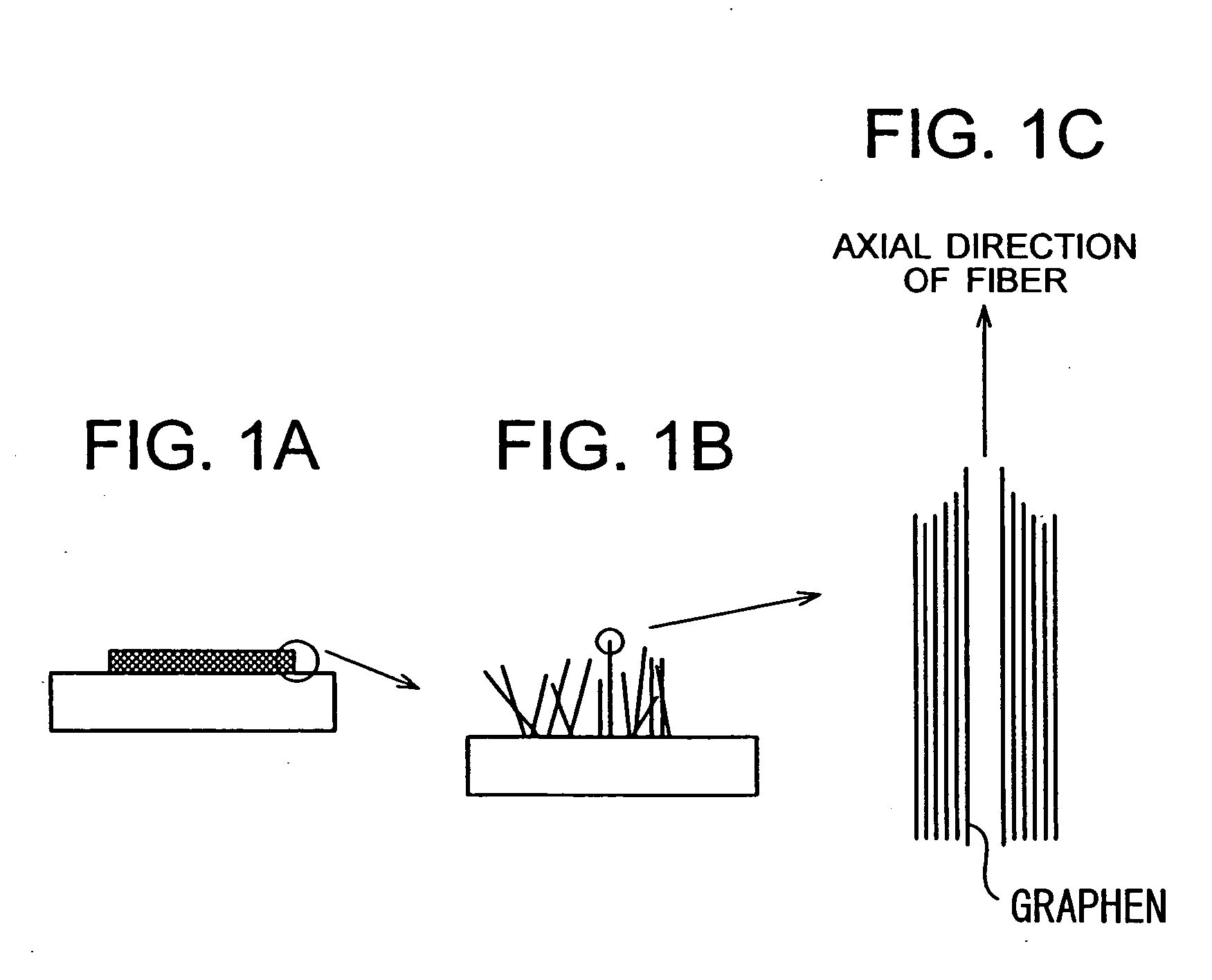
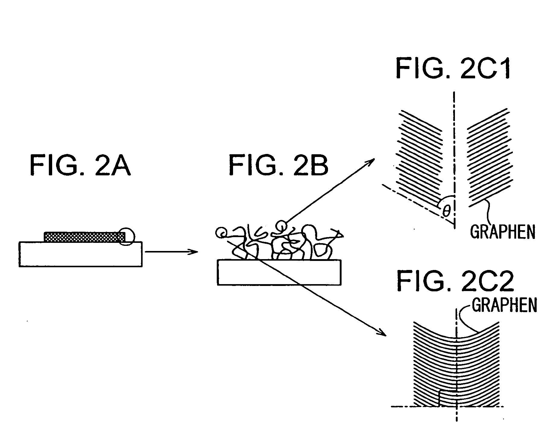
[0187] In this Example 1, the manufacturing method of the invention was applied to the substrate having a catalyst formed thereon to thereby form multiple carbon fibers, and these carbon fibers were used as emitter material.

[0188] First, an explanation will be given of the manufacturing method for a substrate equipped with a catalyst.

[0189] (Step 1)

[0190] In this Example, a quartz substrate was used as the substrate. In this Example, since it is necessary to use electrical connection means for electrical connection with carbon fibers in order to evaluate the electron emission property, there is formed on the substrate an electrode made of TiN the thickness of which is 200 nm.

[0191] (Step 2)

[0192] The proportion of and the conditions for sputter target are adjusted so that Pd may contain approximately 50 atomic percent of Co, thereby a catalyst layer is formed on the TiN electrode so that it has a thickness of 2.5 nm.

[0193] (Step 3)

[0194] Using a photo-resist, multiple resist ...

example 2

[0222] (Step 1)

[0223] In the same way as in the case of the steps 1 to 5 of Example 1, the substrate having a catalyst layer thereon was disposed in the reaction vessel 10, which then was evacuated.

[0224] (Step 2)

[0225] Next, the valves 31 and 33 were opened, then the flowrate of hydrogen that serves as a dilution gas was controlled with the control device 32, and then the dilution gas of Ssccm was introduced into the reaction vessel 10.

[0226] The flowrate of the dilution gas and the conductance of the valve 14 were appropriately adjusted so that the total pressure of the interior of the reaction vessel 10 may be 100000 Pa. Subsequently, an electric power that is applied to the heating mechanism of the heat source 11 was adjusted so that the temperature of the substrate 1 was approximately 600° C.

[0227] (Step 3)

[0228] Next, while the total pressure of the interior of the reaction vessel 10 was being maintained as 100000 Pa and the temperature of the substrate 1 was being maint...

example 3

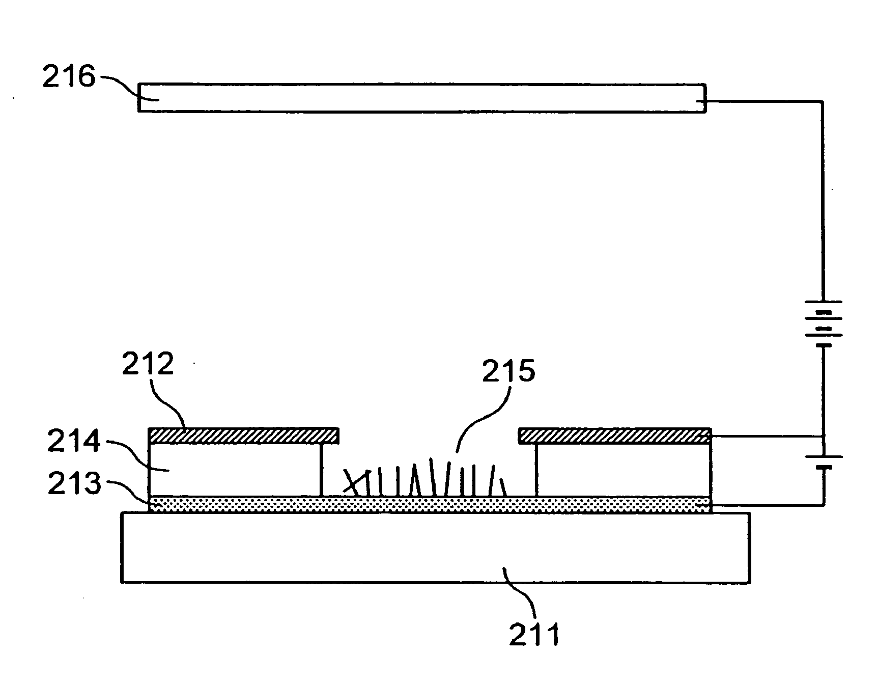
[0235] In this Example, as typically illustrated in FIG. 12, there was fabricated the electron source substratum 61 having disposed in the form of a matrix a large number of the electron emission devices 64 each having multiple carbon fibers 4. Dx1 to Dxm in FIG. 12 represent an m number of the X-directional wired wires 62, and Dy1 to Dyn represent an n number of the Y-directional wired wires 63. The structure of each electron emission device 64 is illustrated as typical sectional views in FIGS. 9A and 9B. In FIGS. 9A and 9B, a reference numeral 111 denotes a substrate, 112 denotes a first electrode (cathode electrode), 113 denotes a second electrode (control electrode), and 114 denotes multiple carbon fibers which are disposed on the first electrode (cathode electrode) 112. The manufacturing method for carbon fibers was executed using the same method as that which was executed in Example 1.

[0236] This electron emission device 64 is of a type that draws electrons out from the carbo...


PUM


Abstract

The invention provides a fiber containing carbon which is less deteriorated in terms of electron emission characteristic, is excellent in terms of reproducibility, and can in addition be formed at a low cost, a substrate and electron emission device using the fiber containing carbon, an electron source using the electron emission device, a display panel using the electron source, and an information displaying/playing apparatus using the display panel, and a method of manufacturing these. The manufacturing method comprises a first step of preparing a substrate (substrate 1) equipped with a catalyst (catalyst layer 3) on its surface; and a second step of causing the fiber containing carbon (carbon fiber 4) to grow using the catalyst, whereby the second step comprises, in order to decrease, from a midway point of time in this step, the growth rate at which the fiber containing carbon grows, a sub-step of controlling the growth conditions for the fiber containing carbon.

Description

BACKGROUND OF THE INVENTION [0001] 1. Field of the Invention [0002] The present invention relates to a fiber containing carbon and a method of manufacturing the same, and to an electronic device such as an electron emission device using a fiber containing carbon, a circuit board using a fiber containing carbon as a wiring, and a secondary battery (fuel cell) using a fiber containing carbon as its cathode material, and a method of manufacturing these. Also, the invention relates to an electron source prepared by disposing on a substrate a number of electron emission devices using a fiber containing carbon, and a method of manufacturing it, and to an image display apparatus, such as a flat display, using the electron source and, further, a lamp using an electron emission device and a method of manufacturing these. Also, the invention relates to an information displaying / playing apparatus, such as a flat television, which can display and play various kinds of informations or signals su...

Claims


Application Information

Patent Timeline
IPC IPC(8): B82B3/00C01B31/02D01F9/127D01F9/133H01J1/304H01J9/02H01J29/04H01J31/12
CPCB82Y30/00D01F9/127D01F9/1271D01F9/1273H01J9/025D01F9/1278D01F9/133H01J1/3042D01F9/1275H01J2201/30453
Inventor KITAMURA, SHINTSUKAMOTO, TAKEO
Owner CANON KK
Why Eureka
Try Eureka