Methods and systems for load bank control and operation

a technology of load bank and control system, applied in the direction of power conversion system, measurement device, instrument, etc., can solve the problems of affecting the operation of conventional load bank

Inactive Publication Date: 2005-06-23
POST GLOVER RESISTORS
View PDF5 Cites 26 Cited by
  • Summary
  • Abstract
  • Description
  • Claims
  • Application Information

AI Technical Summary

Benefits of technology

[0015] According to still another embodiment of the invention, a load bank system includes control circuitry configured to provide duty cycle commands corresponding to a desired load. An input is configured to receive power from an electrical power system to be connected to the load bank system. At least one power resistor is provided for select

Problems solved by technology

However, conventional load banks can suffer from a number of disadvantages.
First, adjusting the load that a conventional load bank places upon a connected source (e.g., a generator) can be time consuming, tedious, and inaccurate, as such changes often involve the physical insertion or extraction of one or more resistors into an existing resistor network.
Hence, such load banks typically require changing a load in steps and therefore are limited as to the type of load changes that can be made during the testing procedure as well as the amount of load that

Method used


Image

  • Methods and systems for load bank control and operation
  • Methods and systems for load bank control and operation
  • Methods and systems for load bank control and operation

Examples


Embodiment Construction

[0026] Embodiments of the present invention and their operation are hereinafter described in detail in connection with the examples of FIGS. 1-6, wherein like numbers indicate the same or corresponding elements throughout the figures. These embodiments are shown and described only for purposes of illustrating examples of components, systems, and methods that can be utilized to implement the principles of the invention, and should not be considered as limiting. From these examples, alternative systems, methods or components will be apparent to those of ordinary skill in the art and will be covered by the scope of the present invention.

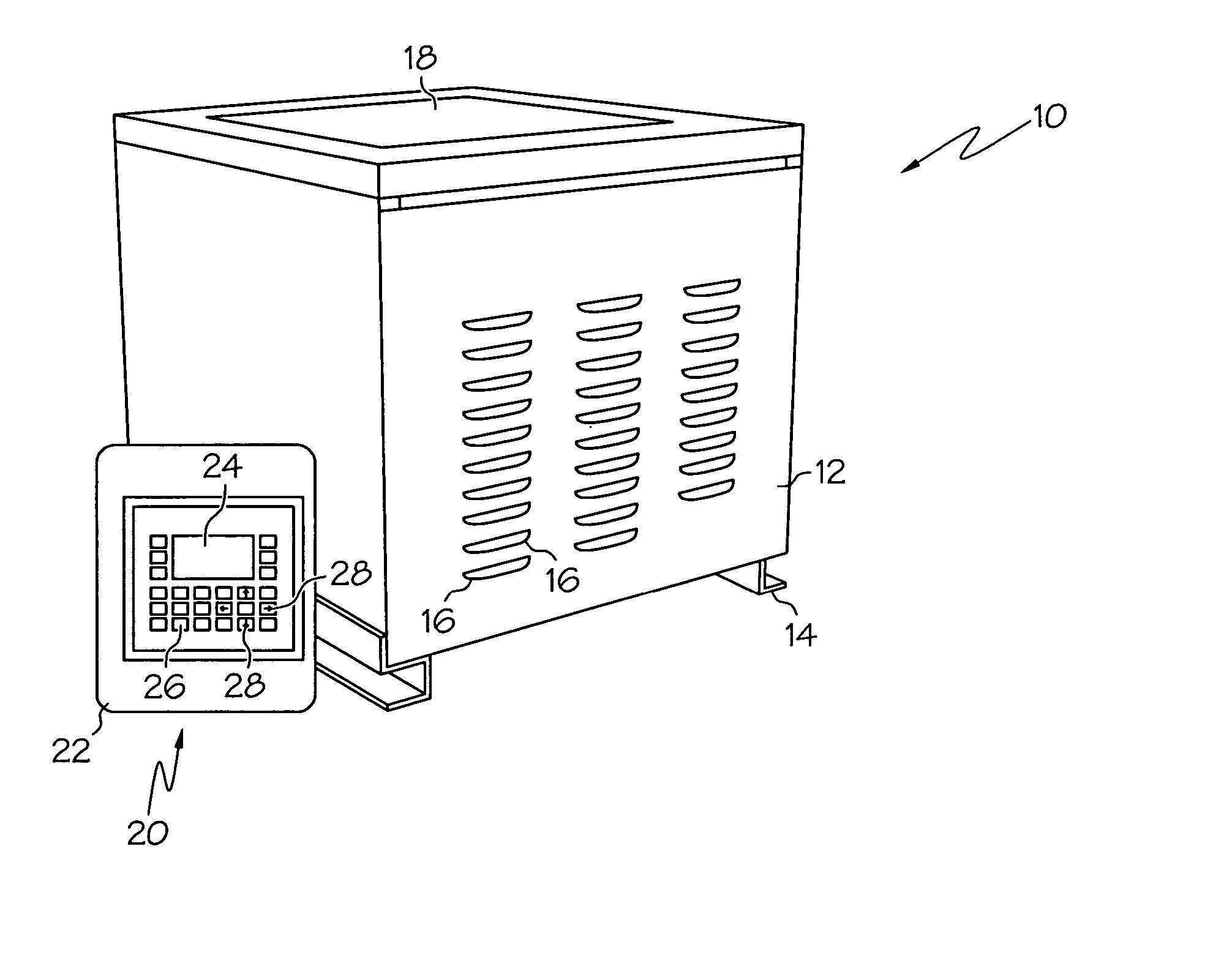
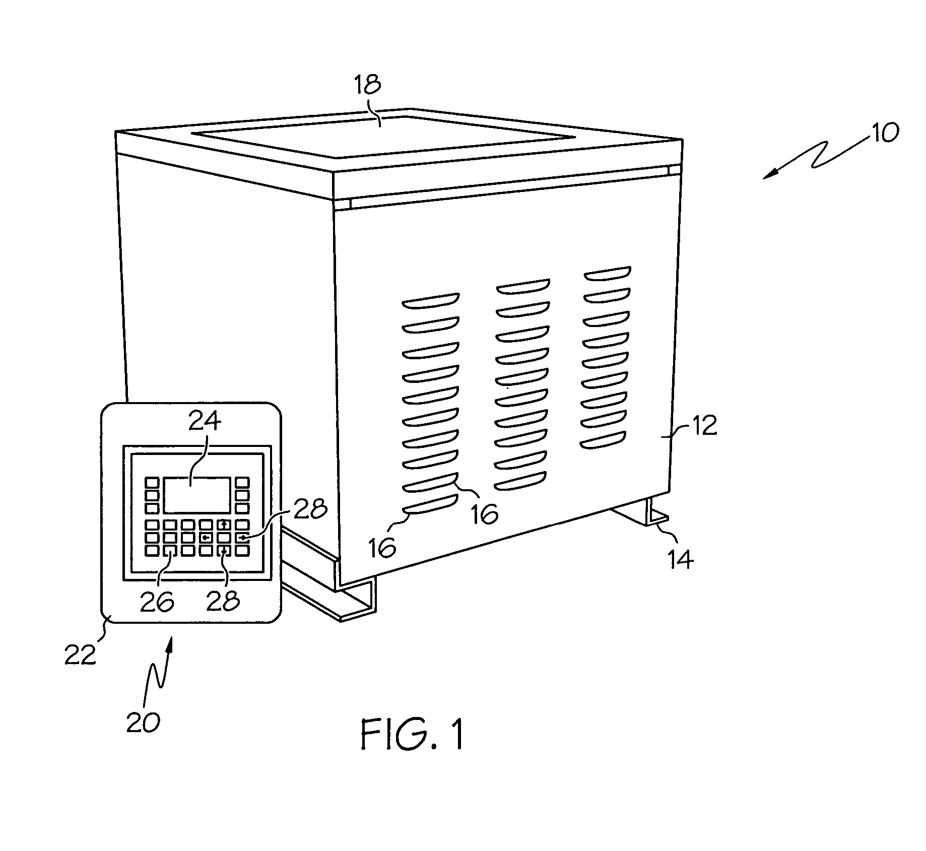
[0027]FIG. 1 is a front perspective view of one illustrative load bank system, including a load bank unit along with its associated HMI programming and control unit, which are made and operate in accordance with principles of the present invention. In this embodiment, a load bank unit 10 is provided along with an HMI (Human Machine Interface) programmi...


PUM


Abstract

An improved load bank system is provided. In one embodiment, the system includes control circuitry configured to provide duty cycle commands corresponding to a desired load. An input is configured to receive power from an electrical power system to be connected to the load bank system. At least one power resistor is selectively connected to the input. High speed solid state electronic switching circuitry is configured to rapidly switch according to the duty cycle command from the control circuitry in order to rapidly and sequentially permit current flow and prevent current flow through the resistor according to the duty cycle command. The effective resistance presented to an electrical power system to be connected at the input is thereby modified. Other load bank systems and load bank units are provided, as well as computer implemented and other methods for controlling a load bank system.

Description

CROSS-REFERENCE TO RELATED APPLICATION [0001] This application claims the benefit of U.S. Provisional Application No. 60 / 524,167, filed Nov. 21, 2003, the entire disclosure of which is hereby incorporated herein by reference.TECHNICAL FIELD [0002] The present invention relates generally to methods and systems for load bank control and operation. In particular, embodiments of the present invention relate to such methods and systems that include programmable digital electronics for defining a testing profile to mimic actual operational parameters, high speed switching electronics for substantially infinite variability of load conditions, local and remote operation through computer network connectivity, and control capability from auxiliary devices. BACKGROUND OF THE INVENTION [0003] A load bank is a testing device that sets a desired electrical load which is then applied to an electrical power source (e.g., an emergency backup generator), so as to mimic or synthesize the operational l...

Claims


Application Information

Patent Timeline
IPC IPC(8): G01R31/00G01R31/36G05F1/40H02M5/293
CPCH02M5/293
Inventor LOCKER, ANTHONY S.BRUNGS, WILLIAM T.
Owner POST GLOVER RESISTORS
Why Eureka
Try Eureka