Apparatus for controlling auxiliary equipment of vehicle

a technology for controlling auxiliary equipment and vehicles, which is applied in the direction of vehicle headlamps, optical radiation measurement, lighting support devices, etc., can solve the problems of insufficient illumination of the overtaken side and the opposite side of the controlled vehicle, and it is impossible to effectively operate the image processing device, so as to achieve effective operation of the control apparatus and execute signal processing

Inactive Publication Date: 2005-06-23
HITACHI LTD +1
View PDF19 Cites 30 Cited by
  • Summary
  • Abstract
  • Description
  • Claims
  • Application Information

AI Technical Summary

Benefits of technology

[0015] Consequently, it is possible to effectively execute signal processing for operation of a plurality of auxiliary devices.
[0016] According to the present invention, it is possible to independently control the right and the left headlamps, i.e., their illumination light intensity and illumination beam distance. Moreover, the headlamps are set to a dimming state when the headlamps are turned on and / or when the normal running is in progress and the light intensity of the headlamps is stepwise or continuously increased according to the output of surroundings detection sensor and / or the vehicle information sensor. Accordingly, when using the headlamps, it is possible to assure a field of views as far as possible without dazzling the drivers of other vehicles such as an oncoming vehicle, an overtaking vehicle, and a preceding vehicle.
[0017] According to the present invention, it is possible to effectively operate the control apparatus for controlling the operation of a plurality of auxiliary devices arranged on a vehicle, especially an image processing device.

Problems solved by technology

Accordingly, brightness of the illumination of the overtaken side and the opposite side of the controlled vehicle becomes insufficient.
Accordingly, when identifying an obstacle of high priority, a walker, and a white line on the road, image acquisition and processing are repeated and it is impossible to effectively operate the image processing device.

Method used


Image

  • Apparatus for controlling auxiliary equipment of vehicle
  • Apparatus for controlling auxiliary equipment of vehicle
  • Apparatus for controlling auxiliary equipment of vehicle

Examples


Embodiment Construction

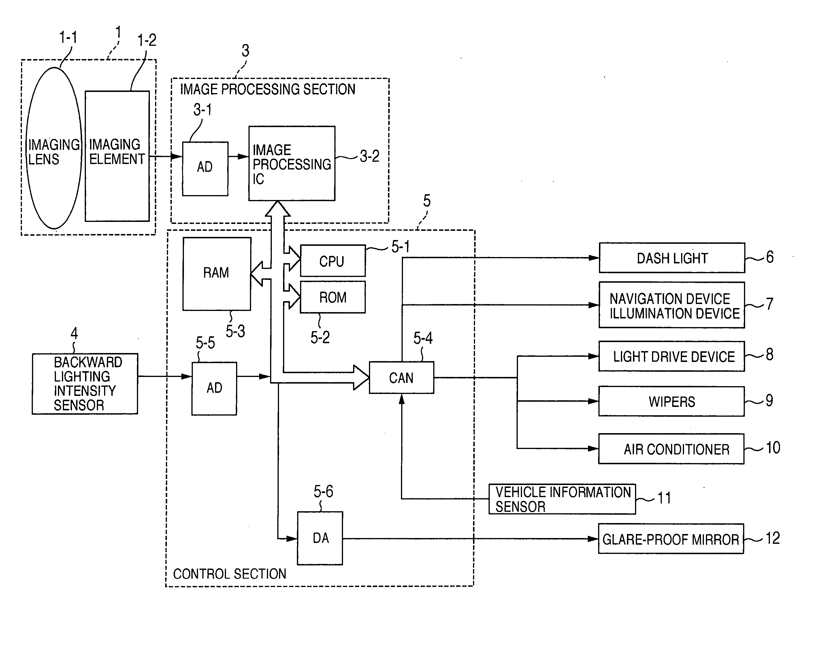
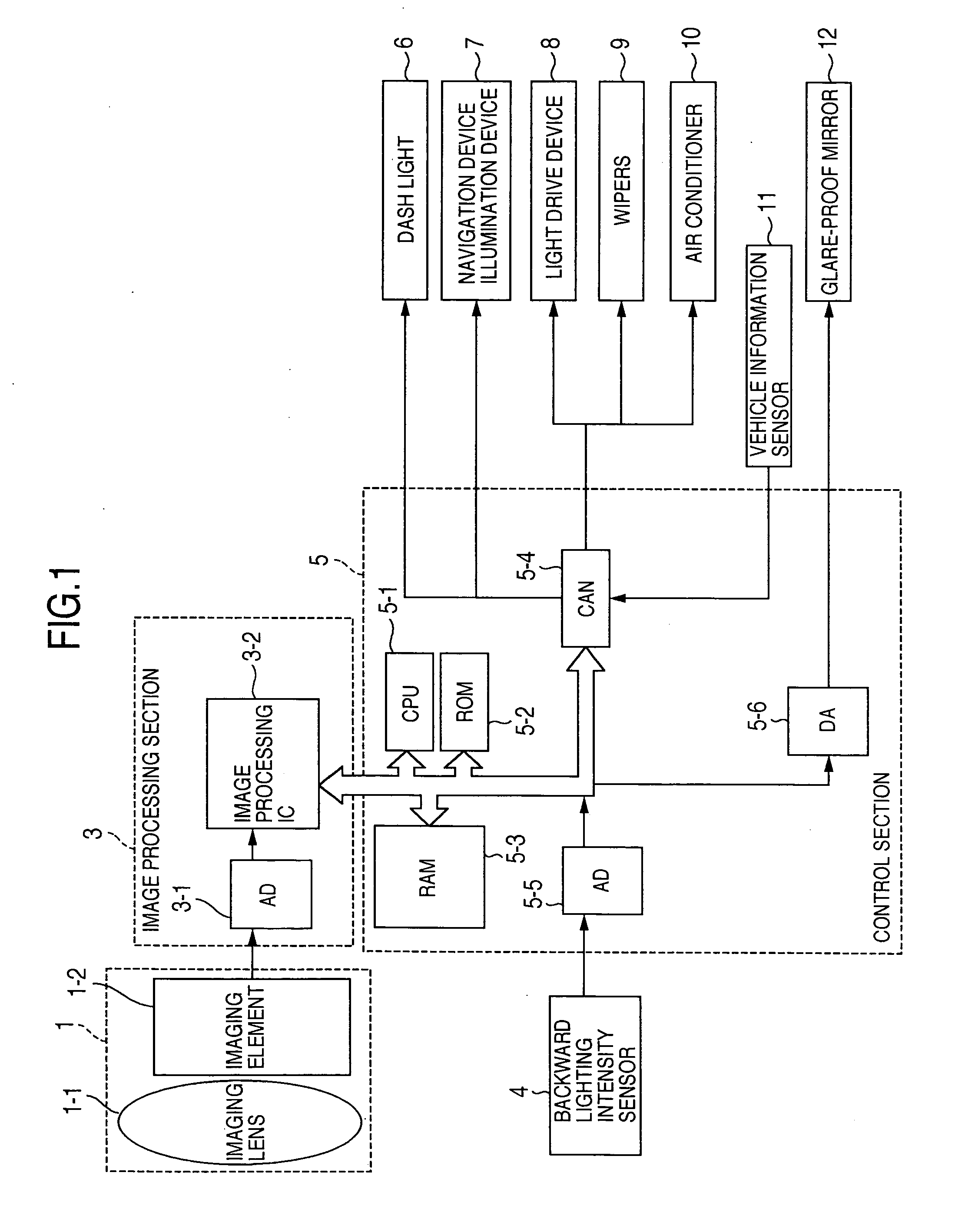
[0034] Description will now be directed to an embodiment with reference to FIG. 1. FIG. 1 shows a system including a sensor, auxiliary equipment, and auxiliary equipment control device mounted on a vehicle. As shown in the figure, this system has a surroundings detection sensor 1, an image processing section 3, a backward luminance sensor for detecting the luminance backward of a vehicle, a control section 5, a dash light 6, a navigation device illumination device 7, a light drive device 8, a wiper, an air conditioner 10 including a defroster, a vehicle information sensor 11 recognizing operation of the controlled vehicle, and a glare-proof mirror having the glare-preventing function.

[0035] The surroundings detection sensor may be any sensor which can detect the condition around the vehicle. For example, it may be an imaging device, a radar device, a photoelectric sensor, or a combination of them. However, hereinafter, the surroundings detection sensor will be explained as an imagi...


PUM


Abstract

An apparatus for controlling operation of auxiliary equipment of a vehicle by receiving an output of a surroundings detection sensor for detecting the surrounding of the vehicle and an output of the vehicle information sensor, for detecting operation of the vehicle, wherein the distance to and the direction of an overtaking vehicle, an oncoming vehicle, or a preceding vehicle and the light intensities of the right and the left headlamps are controlled independently. A plurality of processes required for controlling the vehicle auxiliary equipment are performed by the time division processing.

Description

BACKGROUND OF THE INVENTION [0001] The present invention relates to a control apparatus for controlling auxiliary equipment of a vehicle such as headlamps, side lamps, and wipers and in particular, to a control device for controlling the vehicle auxiliary equipment according to an output from a sensor detecting the condition around the vehicle. [0002] JP-A-2001-519744 (PCT) and the corresponding U.S. Pat. No. 5,837,994 discloses a system for calculating the headlamp setting light intensity as a function of the distance to a preceding vehicle or to an oncoming vehicle and the horizontal position and performs automatic dimming of the right and left headlamps simultaneously. [0003] Moreover, JP-A-11-112968 discloses a system for connecting an image processing device and a plurality of vehicle electronic devices via an in-vehicle LAN. According to this system, in response to an event request from the vehicle electronic device, an image processing result is sent back from the image proce...

Claims


Application Information

Patent Timeline
Patent Type & Authority Applications(United States)
IPC IPC(8): B60R16/02B60H1/00B60Q1/08B60Q1/14B60Q1/18B60R1/00B60S1/08B60S1/54
CPCB60Q1/085B60Q1/1423B60Q1/18B60Q2300/054B60Q2300/056B60Q2300/42B60Q2300/114B60Q2300/312B60Q2300/32B60Q2300/338B60Q2300/41B60Q2300/112
Inventor MONJI, TATSUHIKOFUKUHARA, MASAAKIOUCHI, KATSUOFURUSAWA, ISAOKASUYA, HIROYUKIHIGASHINO, JUNIIDA, FUJIOOTSUBO, KATSUMI
Owner HITACHI LTD
Why Eureka
Try Eureka