

Imaging apparatus and method for producing the same, portable equipment, and imaging sensor and method for producing the same
- Summary
- Abstract
- Description
- Claims
- Application Information
AI Technical Summary
Benefits of technology
Problems solved by technology
Method used
Image

Examples
embodiment 1
[0107] An imaging apparatus according to Embodiment 1 of the present invention will be described.
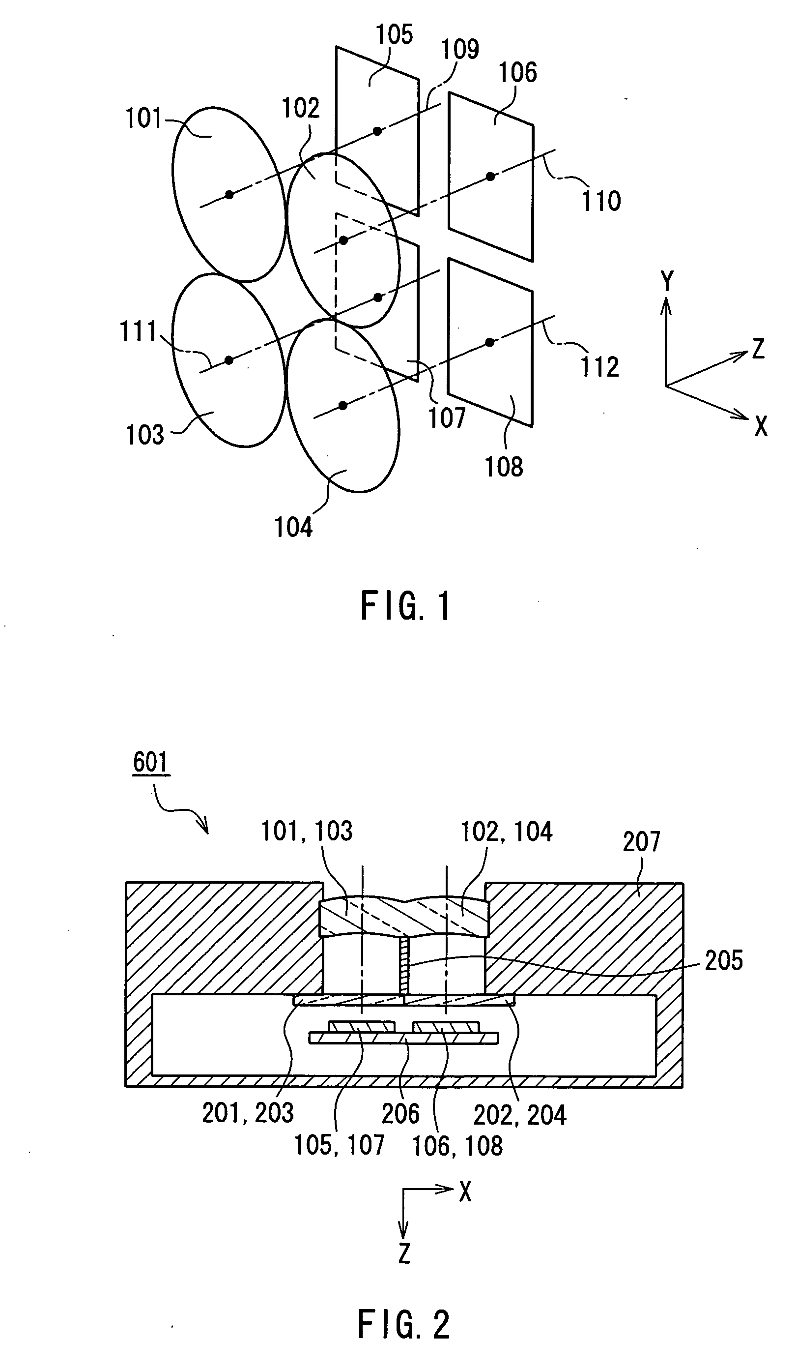
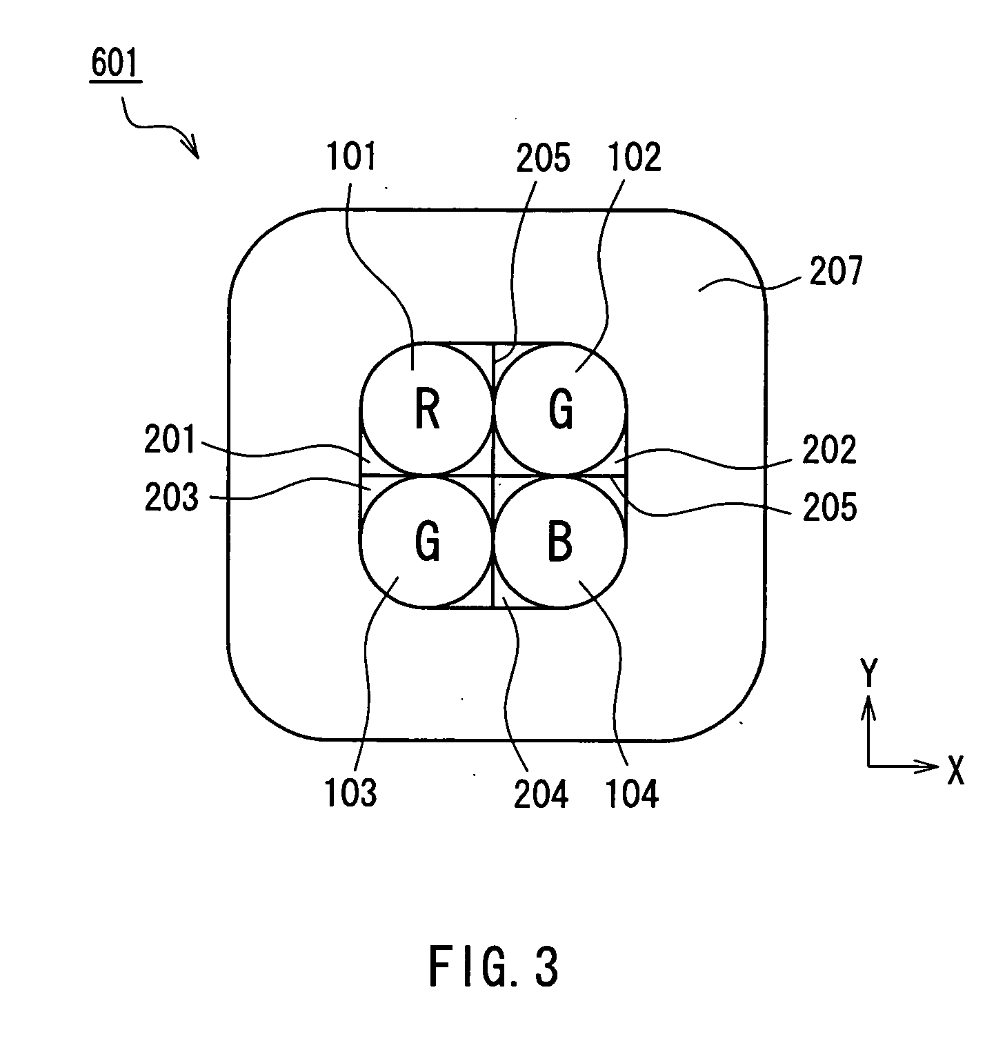
[0108]FIG. 1 is a schematic diagram of the imaging apparatus of Embodiment 1 of the present invention. FIG. 2 is a cross-sectional view of the imaging apparatus of Embodiment 1 of the present invention. FIG. 3 is a plan view of the imaging apparatus of Embodiment 1 of the present invention, viewed from a lens side.
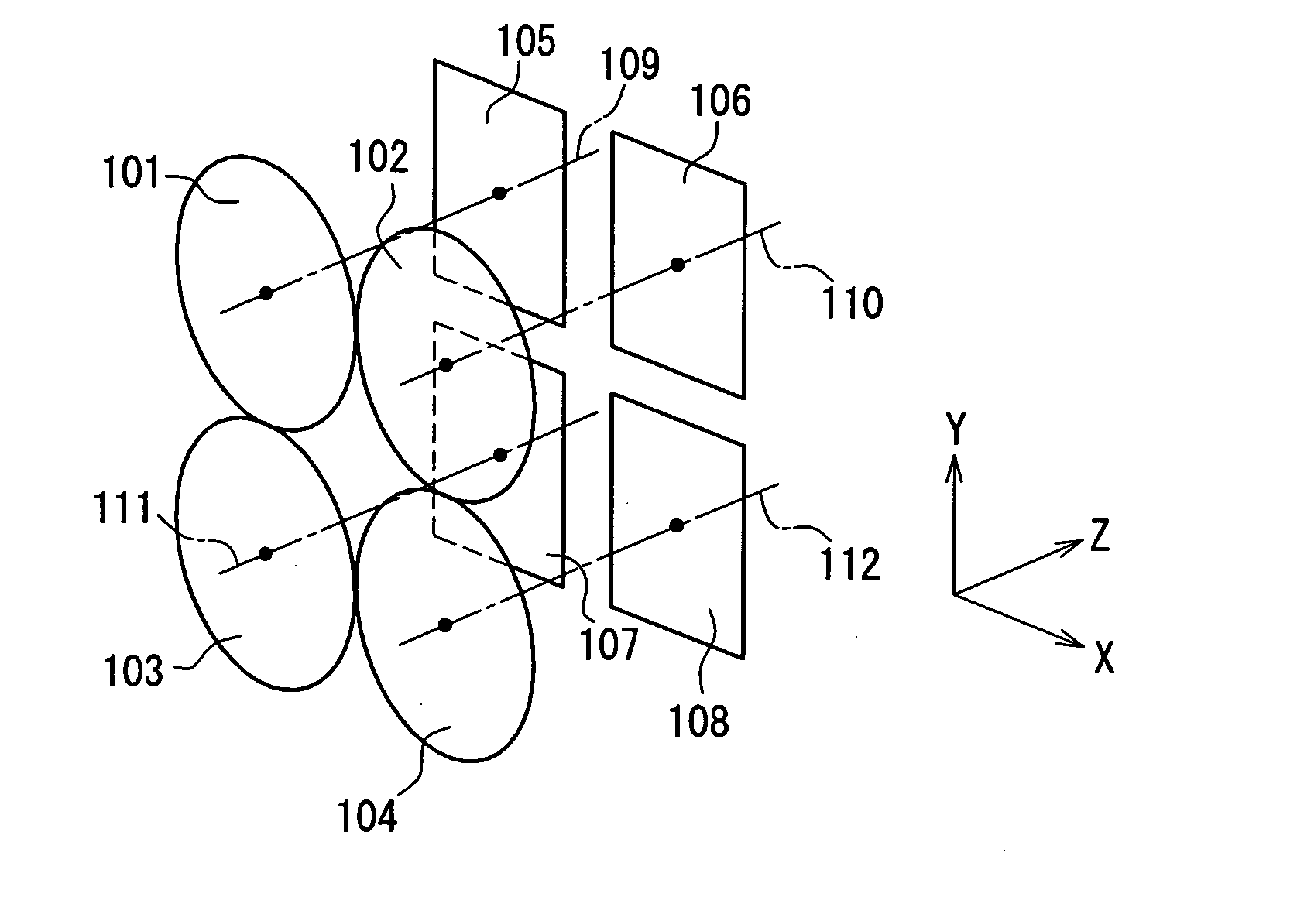
[0109] In FIG. 1, the imaging apparatus of Embodiment 1 has four single lenses 101, 102, 103 and 104, and four imaging sensors 105, 106, 107 and 108 that are in one-to-one correspondence therewith. As shown in FIG. 1, a direction of optical axes 109, 110, 111 and 112 of the single lenses 101, 102, 103 and 104 is represented by a Z-axis, a direction perpendicular to the Z-axis is represented by an X-axis, and a direction perpendicular to the X-axis and the Z-axis is represented by a Y-axis. The positive direction of each of the X-axis, the Y-axis and the Z-axis is represented ...
examples
[0194] Here, a specific shape and size of the imaging apparatus of Embodiment 1 will be shown.
[0195]FIG. 23A is a top view of imaging sensors and lens systems according to an example of the imaging apparatus of Embodiment 1 of the present invention. FIG. 23B is a cross-sectional view of the example of the imaging apparatus of Embodiment 1 of the present invention. In FIGS. 23A and 23B, the same components as those of FIGS. 1 to 22 are indicated with the same reference numerals and will not be explained.
[0196] In FIGS. 23A and 23B, 101, 102, 103 and 104 each indicate an aspherical single lens, which are integrally formed. 207 indicates a housing for the imaging apparatus, to which the integrally formed lens system and the color filters 201, 202, 203 and 204 are fixed. A light shielding plate 205 is provided at a border between adjacent color filters to prevent mixture of light in different wavelength bands. Further, the housing 207 holds one edge of each of first to fourth actuator...
embodiment 2
[0203] A diffraction grating lens in which a diffraction grating is formed on a lens surface will be discussed. Blaze diffraction grating is preferable in terms of improved efficiency. However, a blaze diffraction grating that is optimized with respect to a certain wavelength band (e.g., green), has a high diffraction efficiency with respect to the wavelength band, but has a poor efficiency with respect to other wavelength bands (e.g., red or blue), resulting in unnecessary light. Imaging systems need to be highly efficient with respect to all red, green and blue wavelength bands. Therefore, there has been a limit on the use of a diffraction grating in imaging systems.
[0204] However, in the imaging apparatus of Embodiment 2, a plurality of lens systems and the same number of imaging sensors are provided in a manner such that the imaging sensors are disposed on the optical axes of the respective lens systems as in Embodiment 1. Each lens system corresponds only to a red, green or bl...
PUM
 Abstract
Description
Claims
Application Information