
Wavelength reference system for optical measurements

a wavelength reference and optical measurement technology, applied in the field of measuring optical wavelengths, can solve the problems of limiting the total available bandwidth, difficult to determine bragg wavelength, and uncertainty in the measured bragg wavelength

Active Publication Date: 2005-06-23
OPTOPLAN
View PDF14 Cites 53 Cited by
  • Summary
  • Abstract
  • Description
  • Claims
  • Application Information

AI Technical Summary

Benefits of technology

[0012] The principles of the present invention provide for devices and methods of accurately determining optical wavelengths. Such devices and methods are particularly well suited for determining Bragg wavelengths of FBG elements.
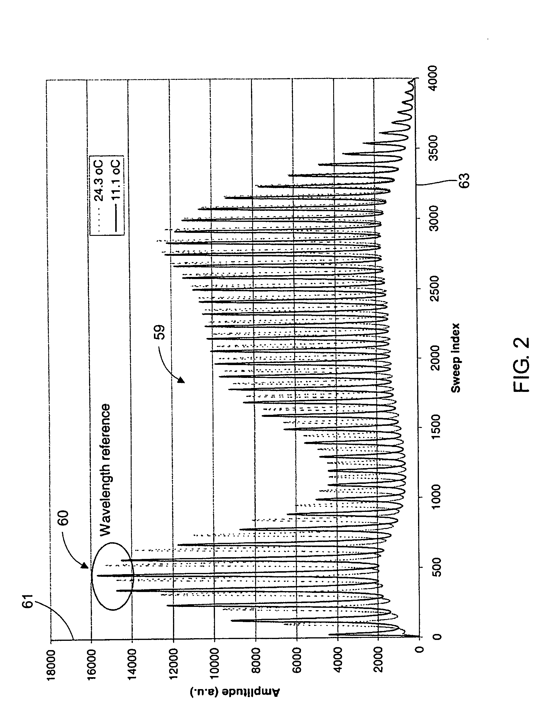
[0014] The wavelength of the identified comb peak is calibrated as a function of temperature. By measuring the temperature of the reference interference filter, or by stabilizing that temperature, the wavelengths of the identified comb peak and of the other comb peaks can be accurately determined and used to measure other wavelengths.

Problems solved by technology

Making the problem of determining Bragg wavelengths more difficult is the fact that broadband sources and tunable filters are subject to gradients and ripples in the filtered light source spectrum that can induce small wavelength shifts in the measured peak wavelengths.
This leads to uncertainties in the measured Bragg wavelength.
One problem that occurs when using one or more reference FBG elements is that they occupy one or more wavelength bands, which limits the total available bandwidth, and hence the number of wavelength multiplexed FBG sensor elements that can be used.
Additionally, reference FBG elements add complexity and cost to the overall system.

Method used


Image

  • Wavelength reference system for optical measurements
  • Wavelength reference system for optical measurements
  • Wavelength reference system for optical measurements

Examples


Embodiment Construction

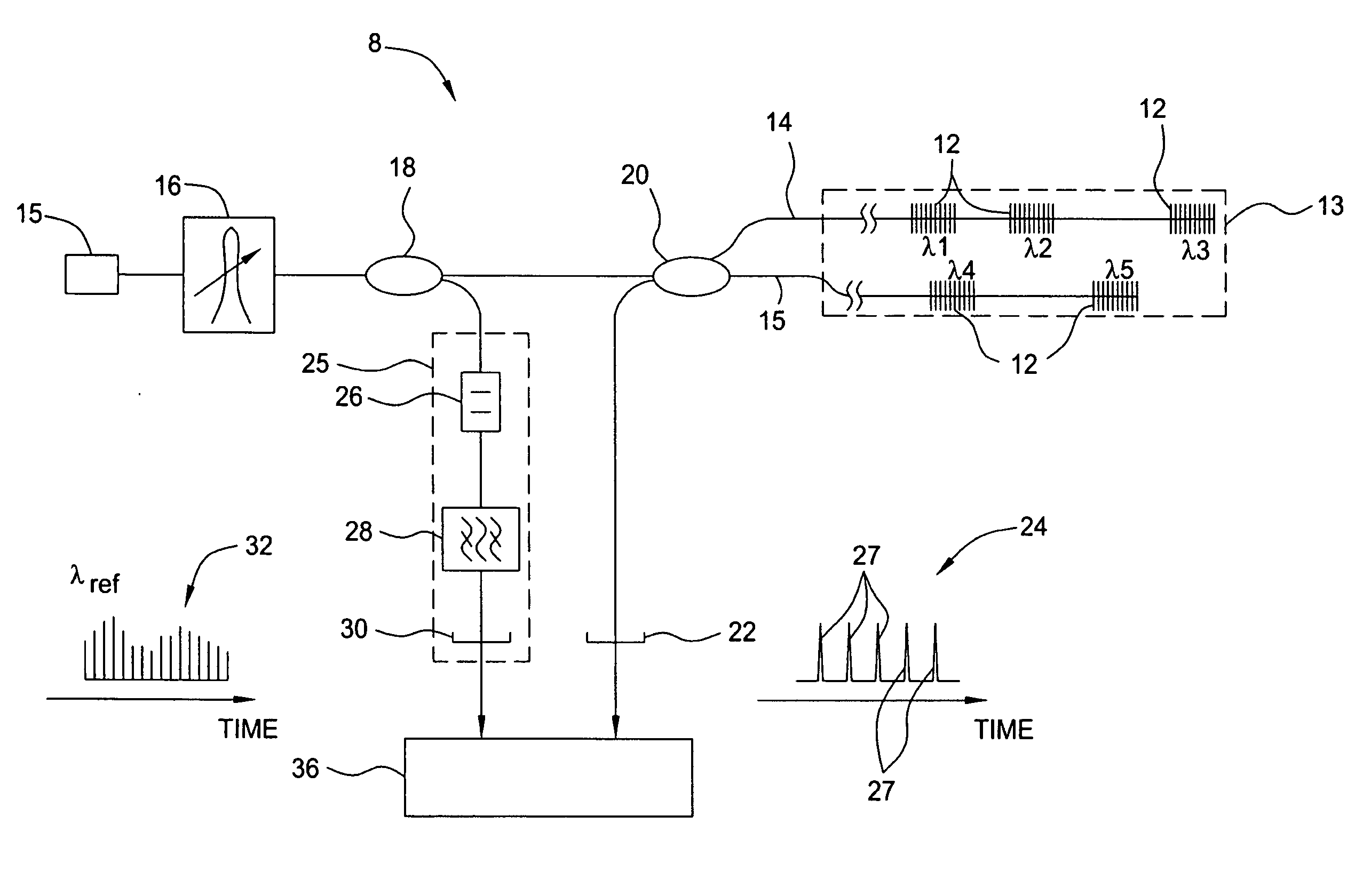
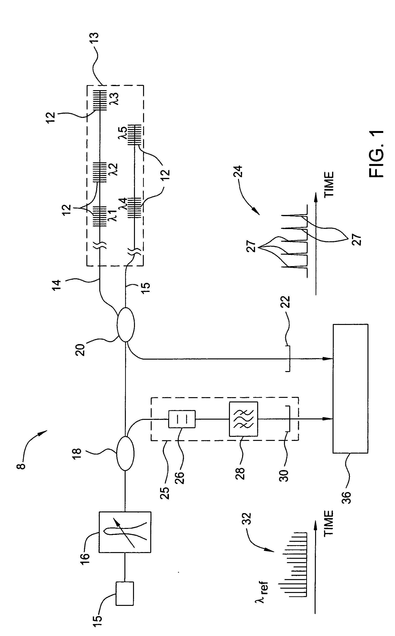
[0025] The present invention provides for a method and apparatus for accurately determining optical wavelengths. Such methods and apparatus are particularly well suited for determining Bragg wavelengths of FBG elements. As such, the principles of the present invention are illustrated in a wavelength measurement system 8 having wavelength multiplexed FBG elements 12 on an FBG sensor array 13, reference FIG. 1. As shown, the FBG sensor array 13 may be comprised of one or more optical fibers 14 and 15. The wavelength measurement system 8 is suitable for measuring pressure and temperature in hostile environments such as occurs in oil wells.

[0026] The wavelength measurement system 8 determines the Bragg wavelengths of the FBG elements 12, which are then used to determine a physical parameter of interest. The wavelength measurement system 8 includes a light source that produces a narrow band, bandwidth-swept light beam having a characteristic spectrum that scans across a wavelength band ...


PUM


Abstract

Devices and methods of accurately determining optical wavelengths, such as the Bragg wavelengths of an FBG sensor array. Wavelength-swept light having a characteristic spectrum is swept over a bandwidth and is applied to an interference filter. The interference filter produces an optical spectrum having one or more reference peaks that are identifiable because of the characteristic spectrum. The optical spectrum is converted into electrical signals having at least one electrical signal that is identifiable because of the characteristic spectrum. The identifiable electrical signal is used by a signal processor as an absolute, high accuracy wavelength reference. Temperature compensation or temperature stabilization can compensate the characteristic wavelength. Fiber Bragg sensor systems can use the wavelength reference to determine the Bragg wavelength of FBG elements. The characteristic spectrum can be imparted by the light source or an optical element such as a transmission line filter.

Description

BACKGROUND OF THE INVENTION [0001] 1. Field of the Invention [0002] This invention relates to measuring optical wavelengths. More particularly, the present invention relates to wavelength reference systems suitable for use in fiber Bragg grating (FBG) sensor systems. [0003] 2. Description of the Related Art [0004] A fiber Bragg grating (FBG) is an optical element formed by photo-induced modulation of the refractive index of the core of an optical fiber. An FBG element reflects light having a wavelength within a narrow bandwidth that is centered on a wavelength that is referred to as the Bragg wavelength. The Bragg wavelength depends not only on the optical fiber itself, but also on physical parameters such as temperature and strain that impact on the refractive index of the optical fiber. Therefore, FBG elements can be used as sensors to measure such physical parameters since, after proper calibration, the Bragg wavelength provides an absolute measure of the physical parameters. [00...

Claims


Application Information

Patent Timeline
IPC IPC(8): G01J3/28
CPCG01J3/28G01J3/1895G01D5/35383G01J3/26
Inventor KRINGLEBOTN, JON THOMASNAKSTAD, HILDETHINGBO, DAG
Owner OPTOPLAN
Learn More