Cabinet and additional device

a technology for additional devices and cabinets, applied in the field of cabinets, can solve the problems of difficult to make air exhaustion or suction in the same direction by fans, and the likely increase of the size of the cabinets of the devices contained in the same rack, so as to prevent abrupt or great decrease in maintain the efficiency of forced air cooling, and avoid unnecessarily high levels of fan performance

Inactive Publication Date: 2005-06-23
FUJITSU LTD
View PDF10 Cites 15 Cited by
  • Summary
  • Abstract
  • Description
  • Claims
  • Application Information

AI Technical Summary

Benefits of technology

[0062] In a fourth additional device according to the present invention, the second conductive cabinet of the above-described third additional device has a second aperture to serve as a bypass path for ventilation in the process of the forced air cooling which is provided between the additional device and another additional device disposed adjacent to the additional device. When another additional device is disposed adjacent to the additional device according to the present invention, and one of the fans provided in these additional devices is in fault or in halt, the other fan in normal operation can compensate all or part of loads of the forced air cooling via the second aperture. This enables a desired device contained in the cabinet of the invention to be adaptable to not only various shapes and dimensions of the additional devices but also various system configurations and operational conditions thereof. Also, this results in preventing abrupt or great decrease in efficiency of the aforesaid forced air cooling.
[0063] A fifth additional device according to the present invention additionally includes a control unit which increases / decreases the rotation speed of fans according to operational conditions of the fans provided in a specific additional device of the present invention and in another additional device that is fitted into the aperture of the first cabinet, to maintain efficiency of the forced air cooling within a prescribed range. Accordingly, the fans provided in actually mounted additional devices and normally operating are able to compensate all or part of loads of the forced air cooling if some of the additional devices are not mounted or the fans in the mounted devices do not normally operate. Consequently, it is possible to maintain high efficiency of the forced air cooling without setting the performance of the fans to an unnecessarily high level, or consuming large power for driving these fans.

Problems solved by technology

Besides, it is difficult to make air exhaustion or suction in the same direction by the fans.
In such a case, it is likely that the size of the cabinets of the devices contained in the same rack increases since the rack needs to have complex ventilation paths for the purpose of compensating or adapting to the exhaustion and suction in various directions.

Method used


Image

  • Cabinet and additional device
  • Cabinet and additional device
  • Cabinet and additional device

Examples


first embodiment

[0102]FIG. 6(a) and FIG. 6(b) are charts to explain the operation of the first and second embodiments of the present invention.

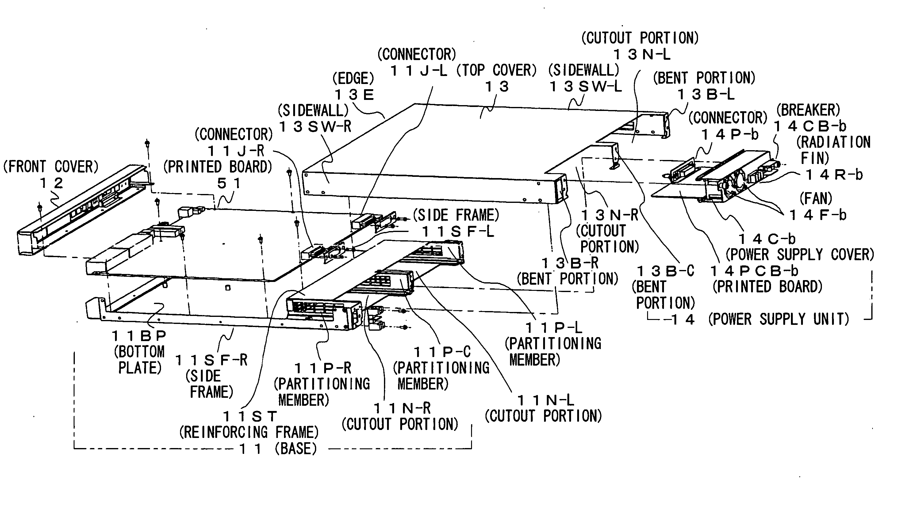
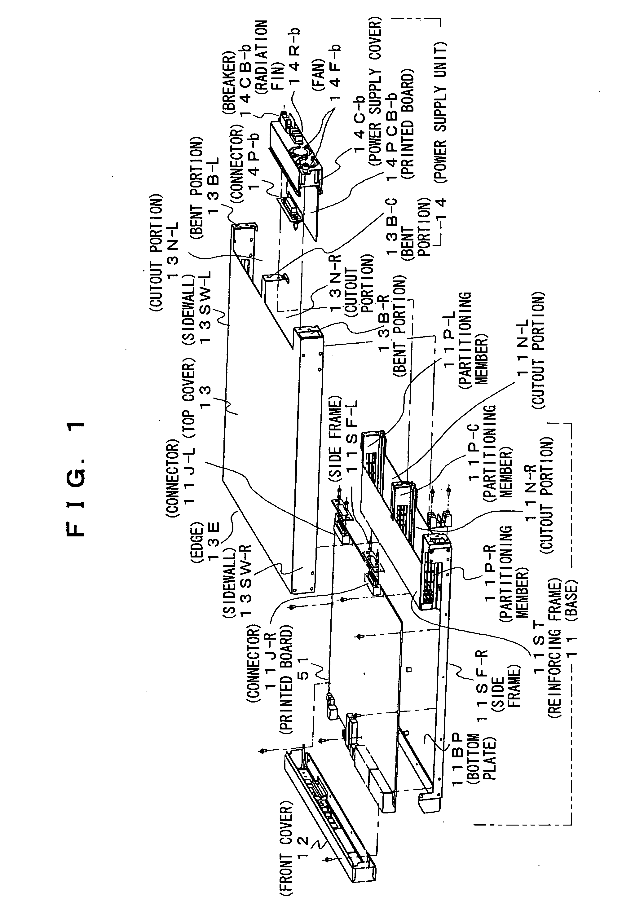
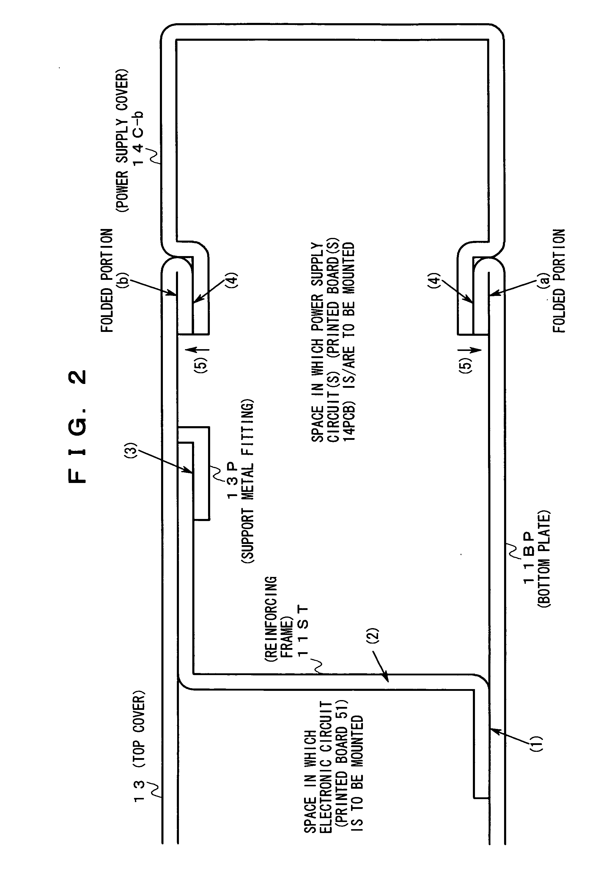
[0103] Hereinafter, the first embodiment of the present invention will be explained with reference to FIG. 1 to FIG. 6(b). Edges of the bottom plate 11BP and the top cover 13 in which the cutout portions 11N-b, 13N-b are formed respectively are folded with predetermined margins as shown in (a) and (b) in FIG. 2. Hereinafter, these edges will be referred to as folded portions.

[0104] Further, as shown in FIG. 2, a support metal fitting 13P is attached to an inner wall of the top cover 13 which is distant from the folded portion with a predetermined length. The support metal fitting 13P is a metal piece with a shape and dimension to insert the reinforcing frame 11ST thereto and support the edge.

[0105] The power supply cover 14C-b is formed in a shape and dimension and of a material so as to ensure elasticity and stiffness to attach / detach the power supply un...

second embodiment

[0121] Hereinafter, the second embodiment of the present invention will be explained with reference to FIG. 1 to FIG. 6(b).

[0122] The characteristics of the second embodiment are the shape, dimension, and pitch of the first slits formed in the partitioning member 11P-C.

[0123] The partitioning member 11P-C has first slits having a shape and dimension, and with a pitch to suppress, as described above, the radiation of high-frequency electro magnetic interference to the power supply unit 14-b and of low-frequency electro magnetic interference to the printed board 51, and in addition, to form bypass paths coupled to each other with a desired degree of tightness between two ventilation paths from the suction port formed in the front cover 12 to the fans 14F-R, 14F-L.

[0124] Incidentally, the first slits in the partitioning members 11P-R, 11P-L may be similarly formed with such shape and dimension and at such a pitch as described above.

[0125] In this embodiment, paths for bi-directiona...

third embodiment

[0129]FIG. 7 is a diagram showing the detailed structure of the third embodiment of the present invention.

[0130] In the drawing, an office power source is connected to an input of a power supply circuit 14PS-b provided in the power supply unit 14-b (disposed on the printed board 14PCB-b) via a not-shown terminal board (assumed here to be disposed on the power supply cover 14C-b), and an output of the power supply circuit 14PS-b is connected to the following terminals provided in the fan 14F-b and to a corresponding pin of the connector 14P-b.

[0131] (1) A terminal used for supplying power (power for fan driving) to the fan 14F-b.

[0132] (2) A terminal used for supplying a control signal indicating one of two different rotation speeds to be set for the fan 14F-b (assumed here for simplicity to indicate that the rotation speed is to be set higher when its logical value is ‘1’ and indicate that the rotation speed is to be set low when its logical value is ‘0’).

[0133] (3) A terminal u...


PUM


Abstract

It is an object of the present invention to provide a cabinet capable of containing various devices and securely attaching/detaching an additional device thereto/therefrom, and to provide an additional device. In order to achieve the object, a cabinet according to the present invention includes: a conductive cylinder having an aperture into which the additional device is fitted by insertion and containing an electronic device, the aperture having a folded edge, the additional device operating in parallel with the electronic device; and a reinforcing member supported with a portion of an inner wall of the cylinder and disposed on a boundary between two areas inside the cylinder where the electronic device and the additional device are disposed respectively, the portion of the inner wall being more inside than the folded portion of the aperture.

Description

CROSS REFERENCE TO RELATED APPLICATION [0001] This application is based upon and claims the benefit of priority from Japanese Patent Application No. 2003-421992, filed on Dec. 19, 2003, the entire contents of which are incorporated herein by reference. BACKGROUND OF THE INVENTION [0002] 1. Field of the Invention [0003] The present invention relates to a cabinet configured to contain a desired device and to have, on a side portion thereof, an additional device which operates in association with or in parallel with the desired device, and it relates to the additional device. [0004] 2. Description of the Related Art [0005] In recent years, various operators employ cabinets in compliance with the EIA standard or the JIS standard to accommodate many devices such as routers and servers of a data communication network which are given maintenance and expansion when necessary, the cabinet containing these devices together in the same site or office premise (may be a single rack). [0006]FIG. ...

Claims


Application Information

Patent Timeline
Patent Type & Authority Applications(United States)
IPC IPC(8): H05K5/02H05K7/14H05K7/20H05K9/00
CPCH05K7/1487H05K9/0062H05K7/20727
Inventor ARAKI, HIDEOKATAGIRI, HIROSHITADA, YOSHIAKI
Owner FUJITSU LTD
Why Eureka
Try Eureka