Method for the manufacture of indexable cutting inserts as well as an indexable cutting insert and a cutting tool having such a cutting insert

Inactive Publication Date: 2005-06-23
SANDVIK INTELLECTUAL PROPERTY AB
View PDF5 Cites 15 Cited by
  • Summary
  • Abstract
  • Description
  • Claims
  • Application Information

AI Technical Summary

Benefits of technology

[0008] An additional object is to provide a manufacturing method by means of which the cutting inserts can be formed with optimum stability and load-carrying

Problems solved by technology

However, inserts made in this way do not have a precision shape, i.e., there are certain shape defe

Method used


Image

  • Method for the manufacture of indexable cutting inserts as well as an indexable cutting insert and a cutting tool having such a cutting insert
  • Method for the manufacture of indexable cutting inserts as well as an indexable cutting insert and a cutting tool having such a cutting insert
  • Method for the manufacture of indexable cutting inserts as well as an indexable cutting insert and a cutting tool having such a cutting insert

Examples


Embodiment Construction

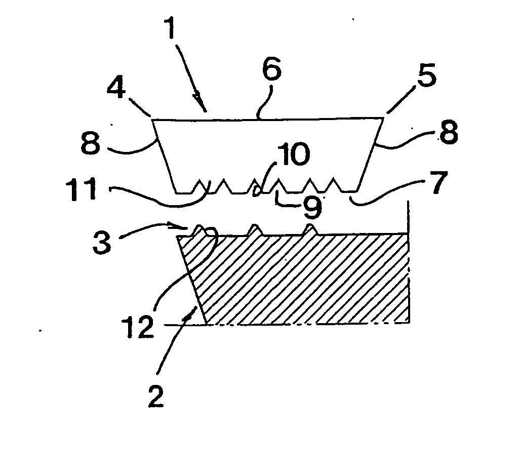
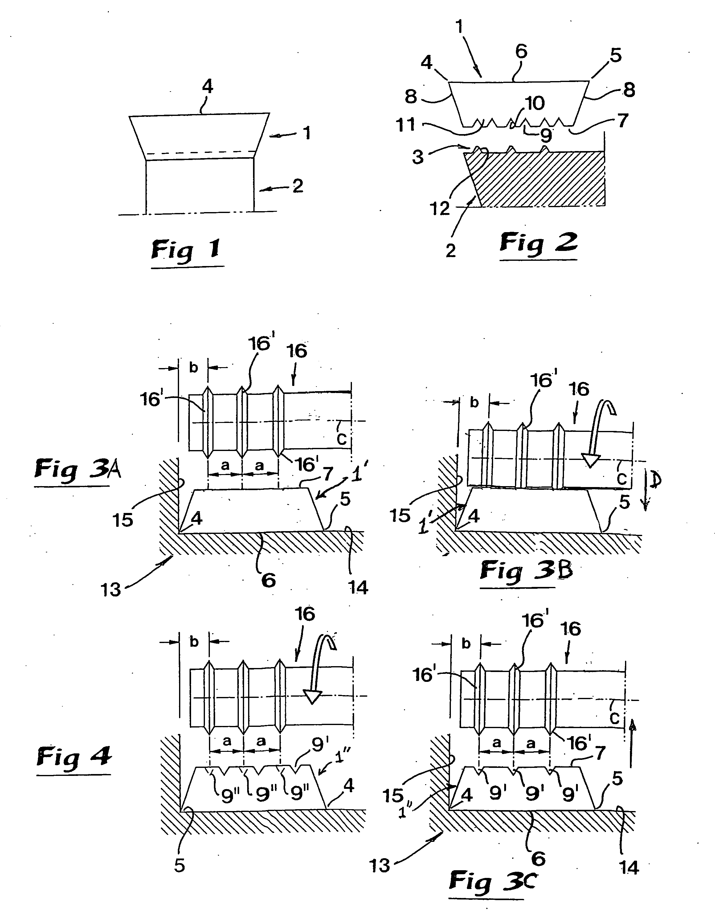
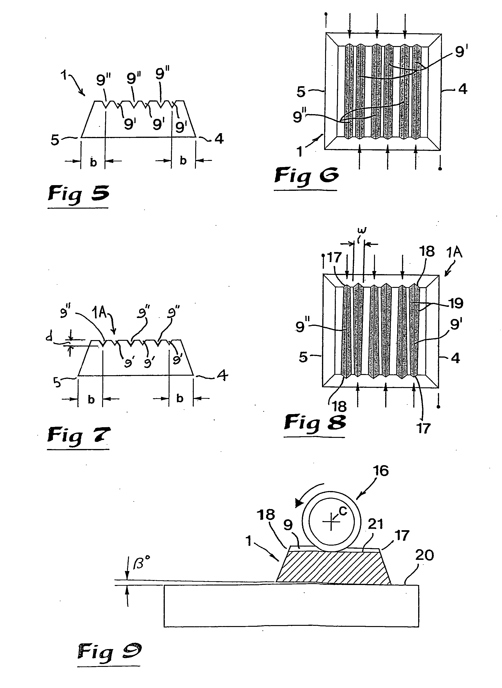
[0045] In FIGS. 1-6 and FIGS. 7-9, respectively, two embodiments are shown of indexable cutting inserts manufactured in accordance with a method according to the invention. It should be emphasized that all drawing FIGS. 1-9 are schematic and simplified. Thus, the cutting inserts in question are illustrated just with one serration connecting surface on the bottom side thereof and with two cutting edges. However, in reality, the cutting inserts are formed with a more or less complicated cutting geometry with means for clamping the cutting insert, e.g. a central hole for a tightening screw.

[0046] In FIGS. 1 and 2, a cutting insert 1 is shown adjacent to a basic body 2 formed with an insert seat 3, which body together with the cutting insert form a complete cutting tool. The cutting insert 1 has two opposite cutting edges 4, 5, the edge 4 of which is indexed to an intended, active position, while the opposite edge 5 is inactive. The cutting insert is delimited by a top side 6, a bottom...


PUM

PropertyMeasurementUnit
Widthaaaaaaaaaa
Depthaaaaaaaaaa

Abstract

An indexable cutting insert has at least first and second cutting edges and first and second edge-location surfaces associated with the first and second cutting edges, respectively. The insert-manufacturing procedure includes forming the first edge-location surface with reference to the first cutting edge, and then forming the second edge-location surface with reference to the second cutting edge. There results an indexable cutting insert having at least two spaced-apart chip-removing cutting edges and a plurality of location surfaces adapted to engage a base body for determining the spatial positions of respective cutting edges, wherein each location surface determines the spatial position of no more than one of the cutting edges.

Description

[0001] The present application claims priority under 35 U.S.C. § 119 to Patent Application Serial No. 0302703-4 filed in Sweden on Oct. 14, 2003, the content of which is hereby incorporated by reference. TECHNICAL FIELD OF THE INVENTION [0002] In one aspect, this invention relates to a method for the manufacture of indexable cutting inserts of the type that comprises at least two spaced-apart, chip-removing edges, as well as location surfaces for determining the space-geometrical position of the edges in relation to a co-operating cutting tool. [0003] In another aspect, the invention also relates to an indexable cutting insert as such. PRIOR ART [0004] Generally, indexable cutting inserts of cutting or chip-removing tools each include at least two edges, which can be worn individually before the cutting insert has to be discarded. Such cutting inserts can be fixed in a so-called insert seat in a basic body, e.g., a milling cutter head, a drill, a boring bar, etc., which together wit...

Claims


Application Information

Patent Timeline
IPC IPC(8): B23C5/20B23B27/14B23B27/16B23C3/30B23C5/22B24B19/02
CPCB23B27/145Y10T407/227B23B2200/165B23B2205/12B23B2260/12B23C3/30B23C5/22B23C2200/165B23C2200/168B23C2210/168B24B19/02Y10T407/22Y10T407/23Y10T409/303752Y10T407/1926Y10T82/10Y10T409/300112B23B2200/164
Inventor LUNDVALL, GORAN
Owner SANDVIK INTELLECTUAL PROPERTY AB
Why Eureka
Try Eureka