Trolley and chock assembly

a technology of chock and trolley, which is applied in the direction of loading ammunition, loading load, transportation items, etc., can solve the problems of affecting the operation of the assembly, and the inability to provide the means for repeatedly and securely, so as to reduce the snag point of the chock and reduce the clogging of the pin opening

Active Publication Date: 2005-06-23
VALENTIN SA
View PDF13 Cites 14 Cited by
  • Summary
  • Abstract
  • Description
  • Claims
  • Application Information

AI Technical Summary

Benefits of technology

[0003] In one embodiment the present invention is a trolley and chock assembly which includes an attachment mechanism for releasably coupling the chock to the trolley and which provides side access to the attachment mechanism for ease of access and operation. In another embodiment, the present invention is a trolley and chock assembly wherein the chock includes a track opening to provide access to the trolley to ensure that the chock consistently slides along the trolley in a smooth manner. In another embodiment, the present invention is a trolley and chock assembly which includes a retaining pin which is generally fully received in the chock to reduce snag points of the chock and trolley assembly. Finally, in yet another embodiment, the present invention is a trolley and chock assembly which includes a cavity which communicates with a pin opening to reduce clogging of the pin opening to ensure that the chock can be repeatedly and securely coupled to the trolley.

Problems solved by technology

However, existing trolley and chock assemblies may be difficult to access and operate, and the chock may not be consistently slidable along the trolley.
Furthermore, existing trolley and chock assemblies may include protruding parts or components upon which a wearer's clothing or other loose items may become snagged.
Finally, existing trolley and chock assemblies may not provide means for repeatedly and securely coupling the chock to the trolley, and may not have sufficient load bearing capabilities.

Method used


Image

  • Trolley and chock assembly
  • Trolley and chock assembly
  • Trolley and chock assembly

Examples


Embodiment Construction

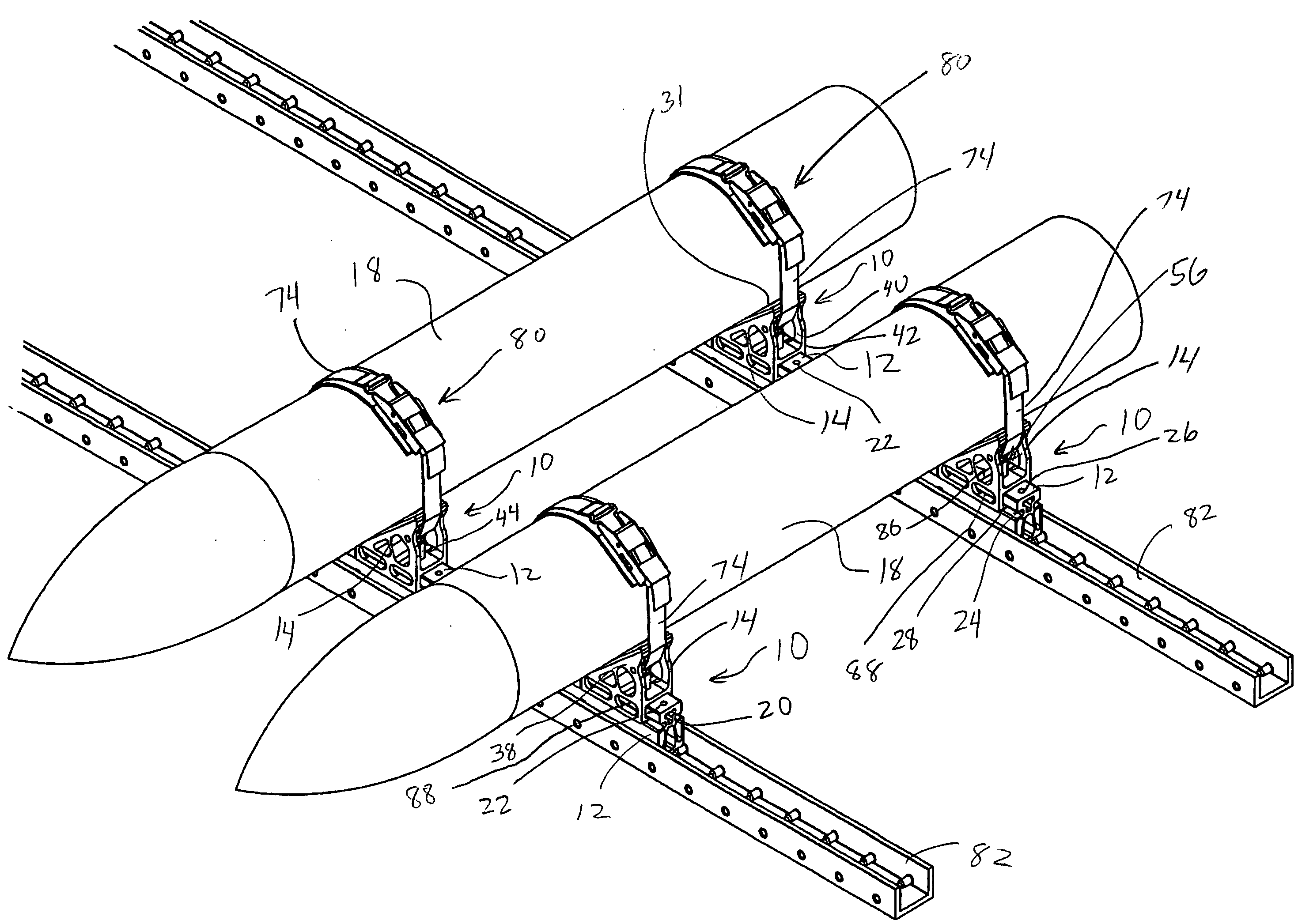
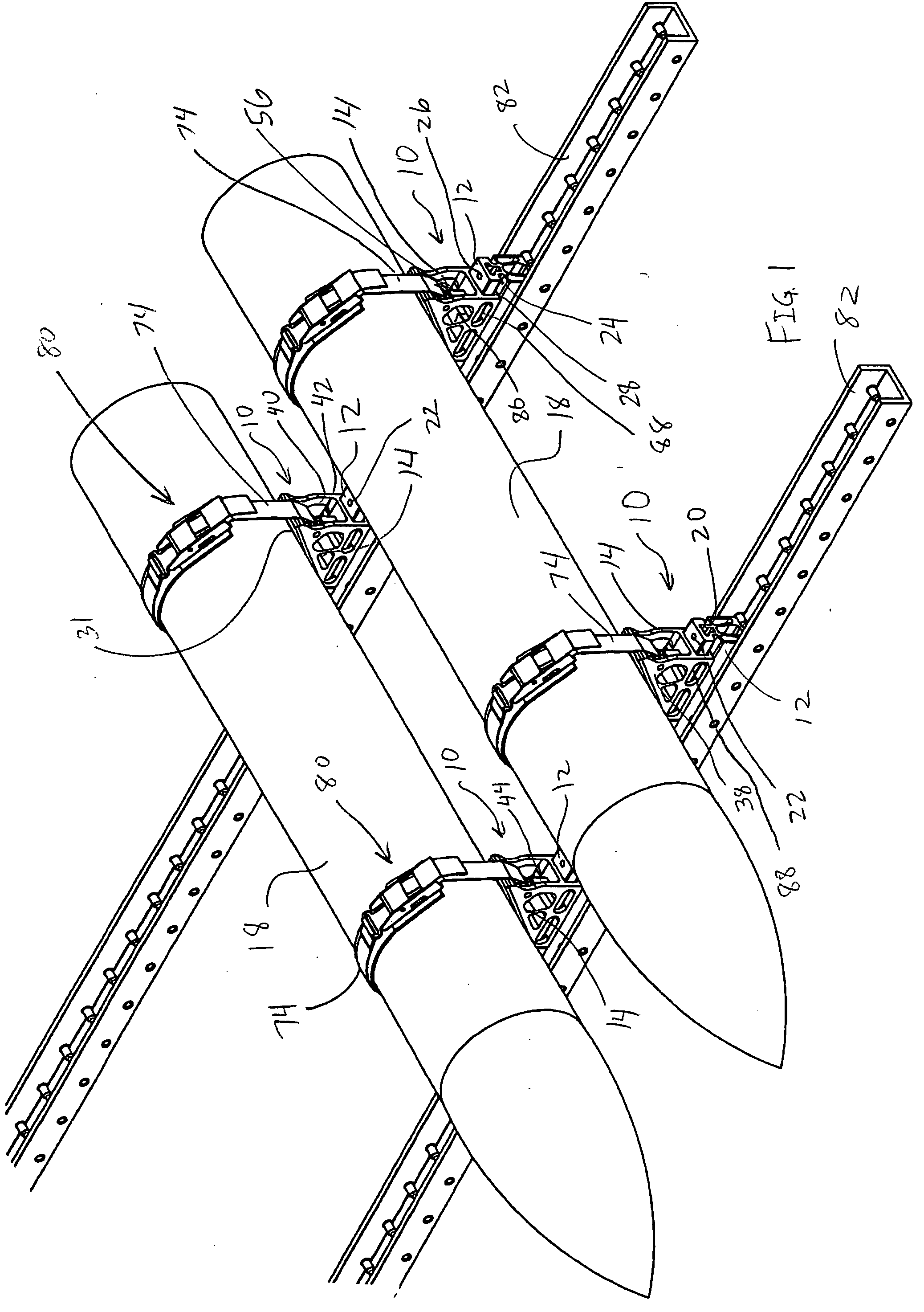
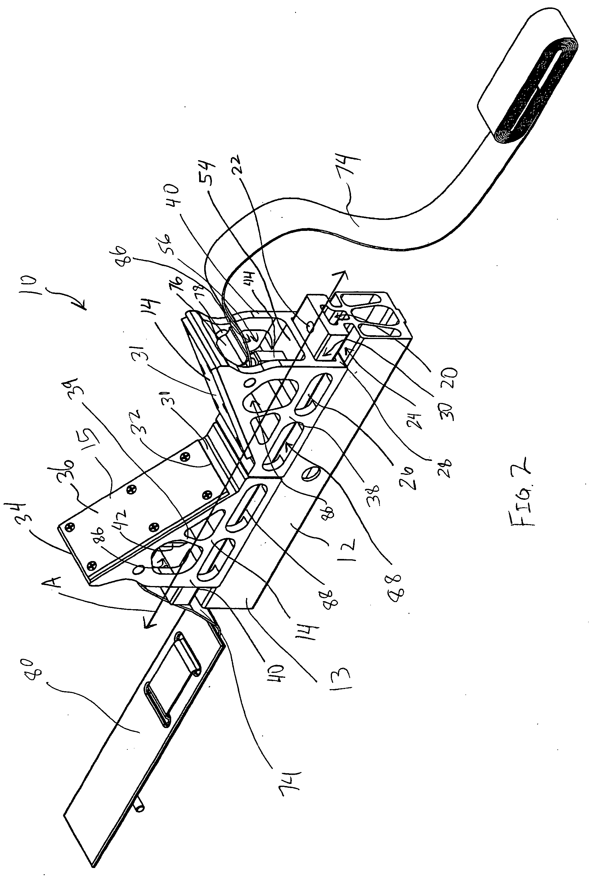
[0021]FIG. 1 illustrates a plurality of trolley and chock assemblies 10, each of which includes a trolley 12 and at least one chock 14 slidable along, and releasably coupled to, the associated trolley 12. For example, as shown in FIG. 2, each chock 14 may be slidably coupled to the associated trolley 12 such that each chock can move in a sliding direction or line A. As shown in FIG. 1, the trolley and chock assemblies 10 may be used to store bombs, munitions, missiles or other components 18 which may be generally cylindrical for transportation, storage, or the like.

[0022] As best shown in FIGS. 4, 10 and 11, each trolley 12 may include a trolley body 13 and may be formed in an extruded shape. Each trolley 12 may have an upper cavity 20 extending along the length thereof. Each trolley 12 may include a set of coupling holes 22 located at the outer ends thereof and communicating with the upper cavity 20. Each coupling hole 22 may extend generally vertically, or generally perpendicular...


PUM


Abstract

A trolley and chock assembly including a trolley and a chock shaped to be slidably coupled to the trolley such that the chock can slide in a sliding direction along the trolley. The chock includes a side opening on a side surface thereof. The trolley and chock assembly further includes an attachment mechanism for releasably coupling the chock to the trolley, and the side opening of the chock provides access to the attachment mechanism in a direction generally perpendicular to the sliding direction.

Description

[0001] The present invention is directed to a trolley and chock assembly, and more particularly, to a trolley and chock assembly wherein the chock is slidably mounted on, and releasably attachable to, the trolley. BACKGROUND [0002] Trolley and chock assemblies are widely used for multiple configuration storage assemblies. For example, in one embodiment, trolley and chock assemblies may be used to store generally components such as bombs, munitions, missiles and the like thereon. However, existing trolley and chock assemblies may be difficult to access and operate, and the chock may not be consistently slidable along the trolley. Furthermore, existing trolley and chock assemblies may include protruding parts or components upon which a wearer's clothing or other loose items may become snagged. Finally, existing trolley and chock assemblies may not provide means for repeatedly and securely coupling the chock to the trolley, and may not have sufficient load bearing capabilities. Accordi...

Claims


Application Information

Patent Timeline
Patent Type & Authority Applications(United States)
IPC IPC(8): B60P7/12B60R11/00B60R13/01F41A9/87
CPCB60P7/12B60R11/00B60R13/01F41A9/87B60R2011/0061B60R2011/0071B60R2011/0084B60R2011/0052
Inventor VALENTINE, HEATH E.
Owner VALENTIN SA
Why Eureka
Try Eureka