Robotic systems for handling objects

a robot system and container technology, applied in the field of automatic handling systems, can solve the problems of increasing labor costs, fading the allure of workers performing tiring and backbreaking outdoor work, and affecting the quality of work, so as to prevent the possibility of damaging the foliage of the plan

Inactive Publication Date: 2005-06-23
CARNEGIE MELLON UNIV
View PDF29 Cites 50 Cited by
  • Summary
  • Abstract
  • Description
  • Claims
  • Application Information

AI Technical Summary

Benefits of technology

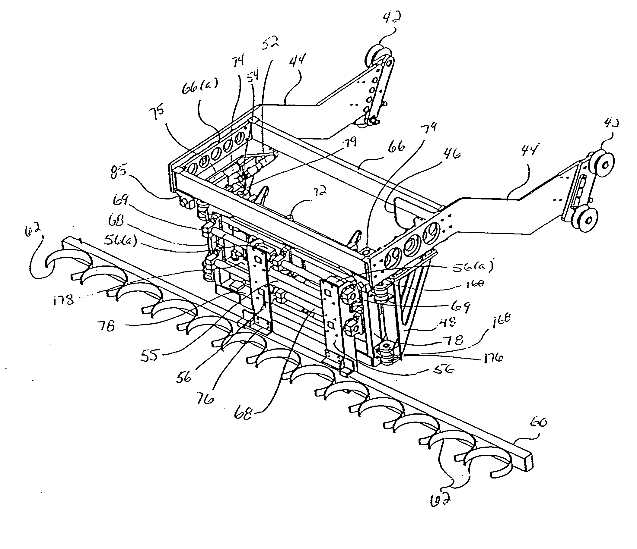
[0044] The grabber head assembly comprises a plurality of grabber members that grip the containers, for example by means of hydraulic actuation. Each of the grabber members in this embodiment may be a semi-circular, or arcuate member defining an opening that receives a container and engages the circumference of the container and not the lip of the container, thus preventing the possibility of damaging the foliage of the plant.

Problems solved by technology

Said labor is getting harder and harder to obtain, requiring continued lobbying-effort in Washington, D.C. to guarantee exemptions from the INS, involves costly recruiting south of the border, transportation to and from their home-towns and their accommodation once in the US and working on site.
In addition, the allure for workers to perform tiring and back-breaking work outdoors is fading when the same labor-pool is being sought for other better-paying and lower-exertion jobs in the US economy such as assembly-, custodial- and other such job-categories.
All these operations are extremely labor-intensive and need to be performed in as compressed a time as possible.
Since labor is the prevalent cost in growing ornamentals (up to 60% according to unofficial surveys), the potential for increasing the competitiveness of the industry through automation in order to reduce manpower requirements, or even smooth out the peak labor-requirements, is potentially very large.

Method used


Image

  • Robotic systems for handling objects
  • Robotic systems for handling objects
  • Robotic systems for handling objects

Examples


Embodiment Construction

[0098] The present invention will be described below in terms of several embodiments of an automated container handling system and related methods for handling containers. It should be noted that describing the present invention in terms of an automated container handling system is for illustrative purposes and the advantages of the present invention may be realized using other structures and technologies that have a need for such apparatuses and methods for handling of objects.

[0099] It is to be further understood that the figures and descriptions of the present invention have been simplified to illustrate elements that are relevant for a clear understanding of the present invention, while eliminating, for purposes of clarity, other elements and / or descriptions thereof found in an automated handling system. Those of ordinary skill in the art will recognize that other elements may be desirable in order to implement the present invention. However, because such elements are well know...


PUM


Abstract

An automated handling system for moving objects from one location to another location is provided with a self-mobile system having a grabber subsystem for grasping objects, including assemblies for movement in four directions, along X, Y and Z axes and through an angle θ. The system also has a translating carriage assembly for moving the grabber subsystem and power supply and drive systems. A sensing device, such as an imager, is provided to determine the geometric position of the objects and to move the grabber subsystem accordingly. Another embodiment of the system is provided as an accessory to a prime mover. It includes an alignment articulation system, a gross advance system, a tine storage system, a loading head system, and pot grabbers. This automated handling system can be used to move plant containers in nurseries from the ground to a trailer bed and/or from a trailer bed to the ground in a variety of container configurations.

Description

CROSS-REFERENCE TO RELATED APPLICATION [0001] This is a continuation-in-part of co-pending U.S. patent application Ser. No. 10 / 120,333, filed Apr. 10, 2002, which is continuation-in-part of U.S. application Ser. No. 09 / 624,752 filed Jul. 24, 2000, which is a non-provisional application that claims priority under 35 U.S.C. §119 from U.S. patent application Ser. No. 60 / 145,330 filed on Jul. 23, 1999.STATEMENT REGARDING FEDERALLY SPONSORED RESEARCH [0002] This invention was made with the United States government support under the following Contract Nos.: 58-1230-8-101 awarded by the United States Department of Agricultural Research Service; NCC5-223 awarded by the National Aeronautics and Space Administration. The United States government has certain rights in the invention.BACKGROUND OF THE INVENTION [0003] 1. Field of the Invention [0004] The present invention is directed generally to an automated handling system. More particularly, the present invention concerns a robotic system for...

Claims


Application Information

Patent Timeline
Patent Type & Authority Applications(United States)
IPC IPC(8): A01G9/08A01G9/10A01G9/14
CPCA01G9/088
Inventor SCHEMPF, HAGENGRAHAM, TODDFUCHS, ROBERTGASIOR, CHRISTIAN THOMAS
Owner CARNEGIE MELLON UNIV
Why Eureka
Try Eureka