Power generation control system, power generation control method, program, and medium

a power generation control and control method technology, applied in process and machine control, electrochemical generators, instruments, etc., can solve the problems of wasting energy each time power-up and power-down operations are performed, preventing the reduction of durability, and stabilizing the operation. , the effect of improving efficiency

Inactive Publication Date: 2005-06-23
UEDA TETSUYA +3
View PDF10 Cites 29 Cited by
  • Summary
  • Abstract
  • Description
  • Claims
  • Application Information

AI Technical Summary

Benefits of technology

[0020] The present invention has been achieved to solve the abovementioned problems with the conventional technology, and aims at providing a power generation control system, a power generation control method, a program, and a medium for preventing the reduction of the durability by, for example, stabilizing the operation of the fuel cell power generation device and improving the efficiency.
[0021] The present invention has also been achieved to solve the problem with the conventional technology, and aims at providing a power generation control system, a power generation control method, a program, and a medium capable of minimizing the waste of energy even when there arise a temporary rise or drop of power load.

Problems solved by technology

Therefore, a large capacity charge / discharge device 46 is required, and the entire device is costly and needs a large installation space.
Since an intermittent operation is performed in the above mentioned conventional fuel cell power generation system (conventional technology 3), energy is wasted each time power-up and power-down operations are performed.
(A) However, in the conventional fuel cell power generation device (conventional technology 1), when an external load command largely changes within a short time, the power control unit 35 has to control the output power by raising and dropping it within a short time, thereby possibly causing the hunting of output power because of the delay of control.
As a result, there can arise the problem that the operation of the fuel cell power generation device becomes unstable, the efficiency of the device is lowered, and the durability is shortened.
(B) Additionally, there has been the problem that the fuel cell power generation system (conventional technology 4) wastes energy when the operation as shown in FIG. 16 which is a graph for explanation of an example of another operation pattern of the conventional fuel cell power generation system (conventional technology 4) is performed.
Thus, energy is wasted in the originally unnecessary activating and stopping operations.

Method used


Image

  • Power generation control system, power generation control method, program, and medium
  • Power generation control system, power generation control method, program, and medium
  • Power generation control system, power generation control method, program, and medium

Examples


embodiment 1

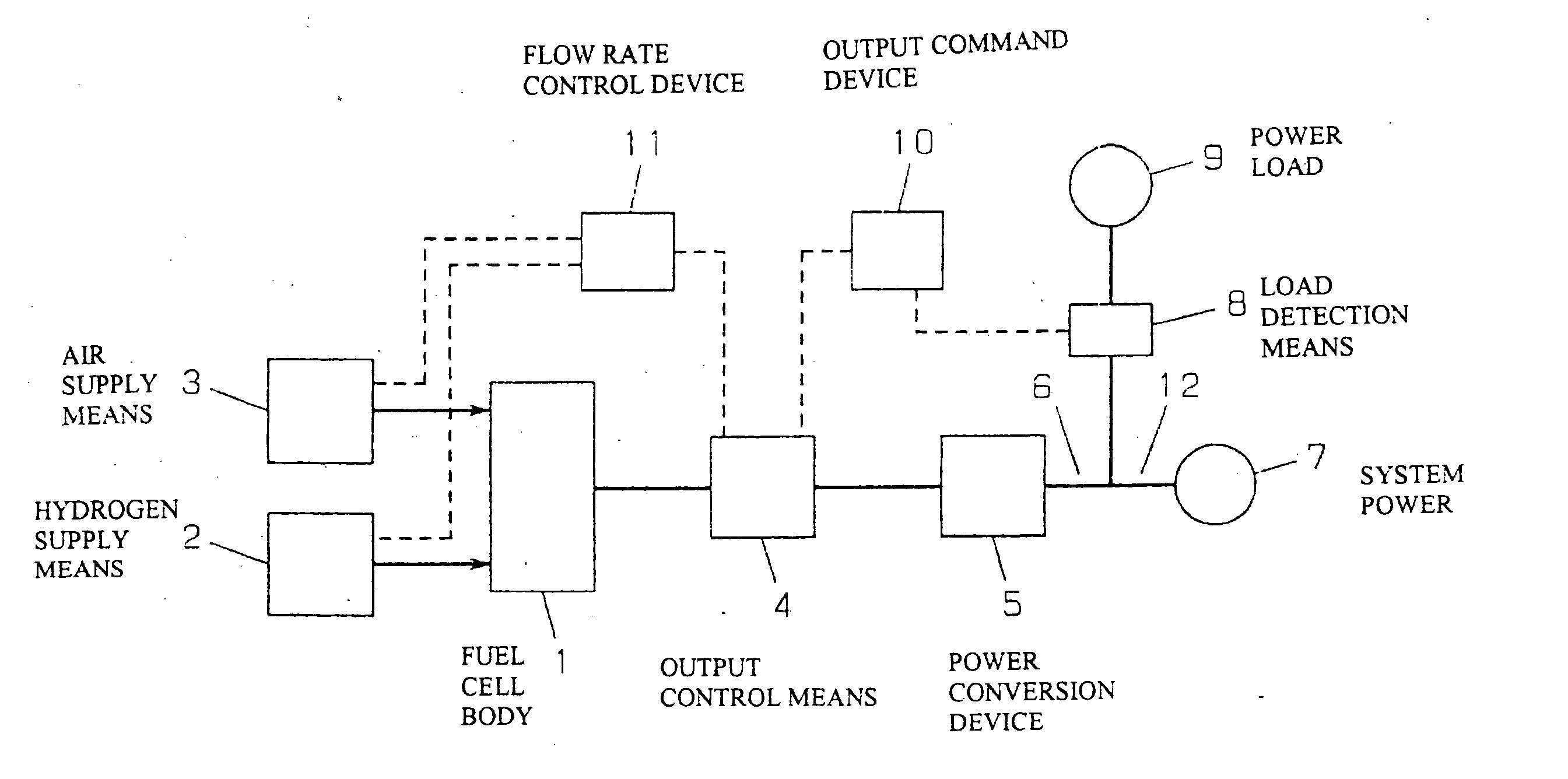
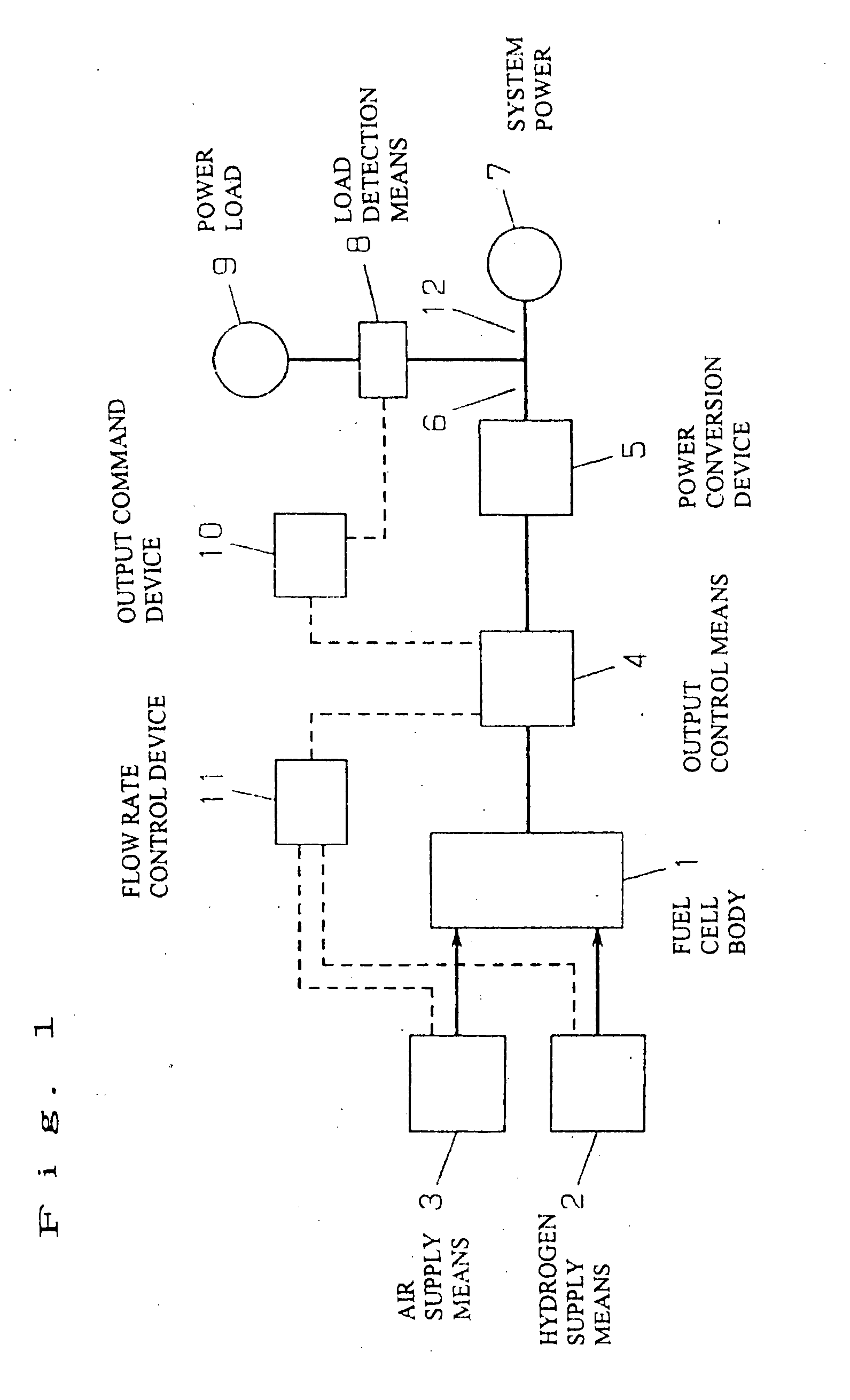
[0159] First, a configuration of a fuel cell power generation device according to a first embodiment of the present invention will be described below by referring to FIG. 1 showing the configuration of the system of the fuel cell power generation device according to the first embodiment of the present invention.

[0160] To a fuel cell body 1, hydrogen supply means 2 represented by a reformer, a hydrogen storage alloy, a hydrogen bomb, etc., and air supply means 3 represented by an air blower, a blower pump, etc. are connected. One terminal of output control means 4 is electrically connected to the fuel cell body 1, and another terminal is electrically connected to a power conversion device 5. An output line 6 is electrically connected to the power conversion device 5, branched in the line, one terminal is electrically connected to a system power 7 through a system power connection line 12 while another terminal is electrically connected to load detection means 8 and a power load 9. O...

embodiment 2

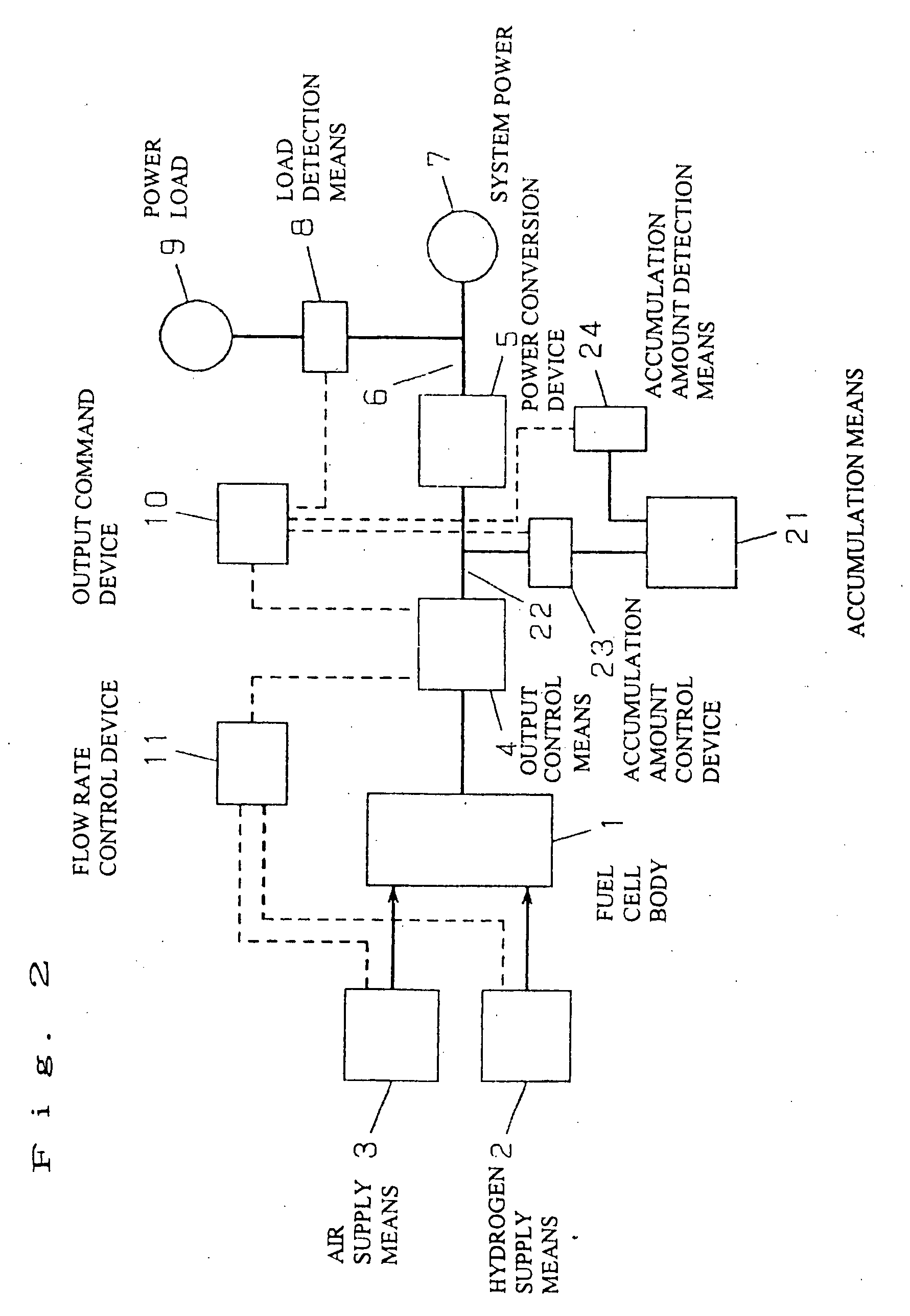
[0170] The configuration of the fuel cell power generation device according to a second embodiment of the present invention will be described below by referring to FIG. 2 showing the configuration of the system of the fuel cell power generation device according to a second embodiment of the present invention. The means also appearing in the above mentioned first embodiment is assigned the same reference numeral, and the explanation is omitted here.

[0171] Accumulation means 21 is branched from a connection line 22 connecting the output control means 4 to the power conversion device 5, and connected through an accumulation amount control device 23. Accumulation amount detection means 24 is connected to the accumulation means 21. An object of providing the accumulation means 21 is to solve the problem with the first embodiment that the economical efficiency is reduced in the system linkage operation by adjusting the power relating to the system power 7 due to the excess or deficient o...

embodiment 3

[0176] Then, the configuration of the fuel cell power generation system according to a third embodiment of the present invention is described below by referring to FIG. 10 showing the configuration of the fuel cell power generation system of the third embodiment of the present invention.

[0177] In FIG. 10, the host 101, output control means 102, and load detection means 103 are serially connected in this order, a load 104 wastes the power connected to the load detection means 103, and a battery 105 is branched and connected from the connection portion between the output control means 102 and the load detection means 103.

[0178] The fuel cell body 101 corresponds to means including the power generation means according to the present invention, the load detection means 103 corresponds to means including the power detection means according to the present invention, the output control means 102 corresponds to means including the power generation control means and the time accumulation m...


PUM

PropertyMeasurementUnit
timeaaaaaaaaaa
timeaaaaaaaaaa
poweraaaaaaaaaa

Abstract

It has been difficult to reduce a waste of energy in a fuel cell power generating process when, for example, a temporary rise or drop of a power load occurs. A fuel cell power generation system includes: load detection means of detecting power requested by a load; and output control means of accumulating a time at which a detected power requested by the load is equal to or larger than a predetermined value when a fuel cell body does not generate power to be supplied to the load, and allowing the fuel cell body to start generating power to be supplied to the load according to a predetermined rule based on an accumulation result.

Description

TECHNICAL FIELD [0001] The present invention relates to a power generation control system, a power generation control method, a program and a medium for supply of power to, for example, a domestic power load using a fuel cell, etc. BACKGROUND ART [0002] (A) FIG. 11 shows a configuration of a conventional fuel cell power generation device (conventional technology 1) disclosed in Japanese Patent Laid-Open No. 7-57753. In FIG. 11, a fuel cell body 31 generates DC power by reaction between hydrogen supplied by hydrogen supply means 32 and oxygen in the air supplied by air supply means 33, and a power converter 34 outputs AC power after converting the DC power into the AC power. At an external load command, a power control unit 35 controls a flow rate control unit 36 and the power converter 34, the flow rate control unit 36 controls the flow rate of the hydrogen supply by the hydrogen supply means 32 and the flow rate of the air supply by the air supply means 33 such that the flow rates ...

Claims


Application Information

Patent Timeline
Patent Type & Authority Applications(United States)
IPC IPC(8): H01M8/04H01M16/00H02J3/38H02J7/34
CPCH01M8/04604H01M8/04626H01M8/0494H01M8/04947H01M8/04955H01M8/04992Y02E60/50H02J3/00H02J3/14H02J3/38H02J7/34H02J2001/004H01M16/006H02J2300/30Y02E60/10H02J2310/58H02J3/144H01M8/04
Inventor UEDA, TETSUYAOGAWA, OSAMUSUZUKI, JIROMIYAUCHI, SHINJI
Owner UEDA TETSUYA
Why Eureka
Try Eureka