Implant system and method of installation thereof

a technology of implants and screws, applied in the field of implants, can solve the problems of increasing the overall cost of installation, affecting the overall performance of the implant, and the tendency of the implant to rotate,

Inactive Publication Date: 2005-06-23
ENNAJIMI ELMEKKI +3
View PDF20 Cites 76 Cited by
  • Summary
  • Abstract
  • Description
  • Claims
  • Application Information

AI Technical Summary

Problems solved by technology

In fact, conventional dental implant systems generally do not adequately distribute the loads and stresses.
These forces often lead to a tendency of the implant to rotate, therefore acting upon softer bone matrix.
However, the possibility of the components loosening and the stress imposed to the bone upon screwing the second part into the implant are two important factors unequivocally remaining with this type of system.
Several problems have also been identified with conventional implant systems and with their use and installation: the metal-implant to metal-abutment fixation requires a screw and a chimney for accessing it.
The use of screws increases the overall cost of the installation.
In addition, screws have a tendency to become loose over time the metal-to-metal interconnection between the a...

Method used


Image

  • Implant system and method of installation thereof
  • Implant system and method of installation thereof
  • Implant system and method of installation thereof

Examples


first embodiment

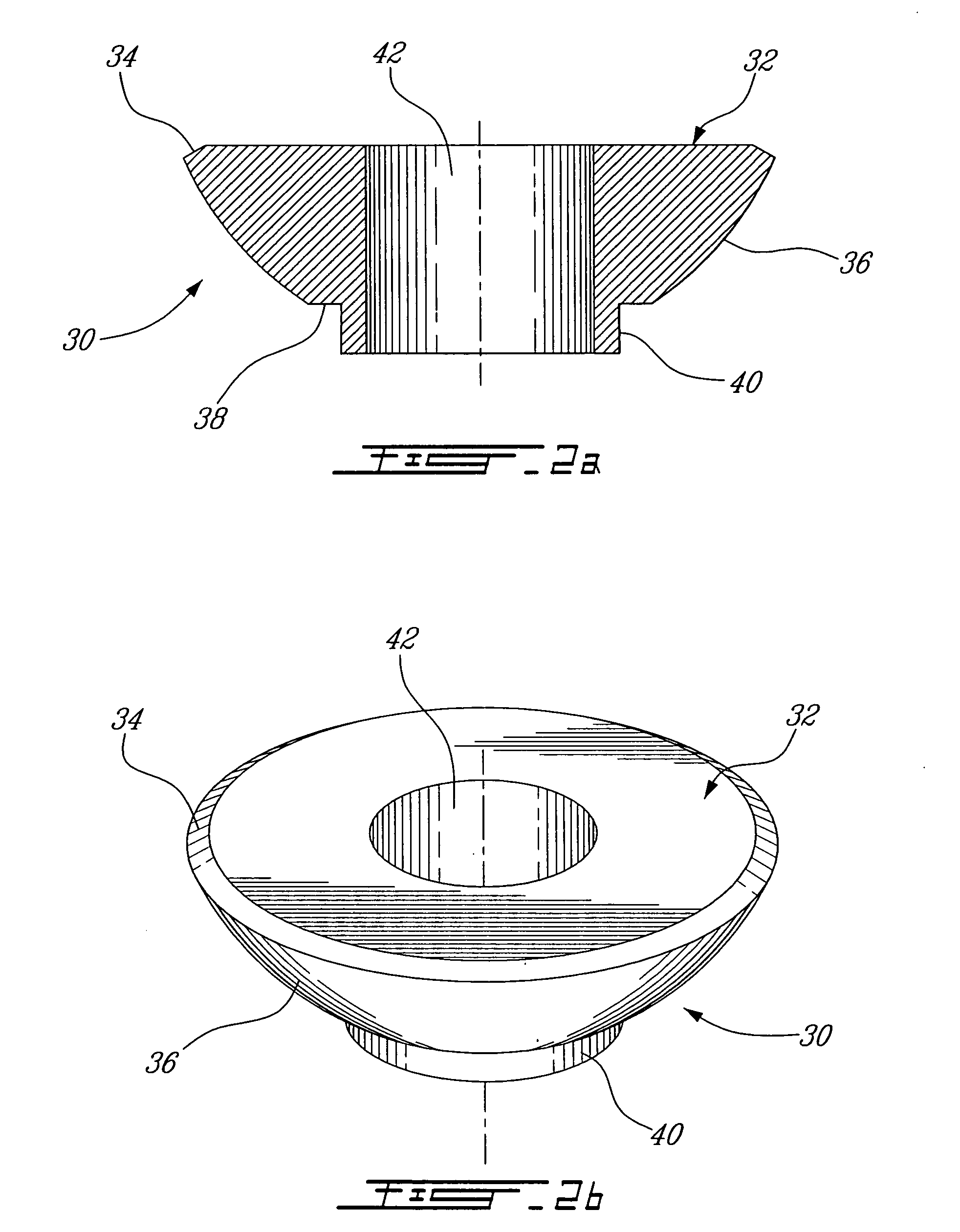
[0078] Referring now to FIGS. 1a to 4b, an implant system according to the present invention will be described. The implant system includes a prosthesis support in the form of the combination of an abutment 10 illustrated in FIGS. 1a and 1b and a collar member 30 illustrated in FIGS. 2a and 2b; and an implant 46 illustrated in FIGS. 3a and 3b. FIGS. 4a and 4b illustrate the assembly of the prosthesis support and the implant 46.

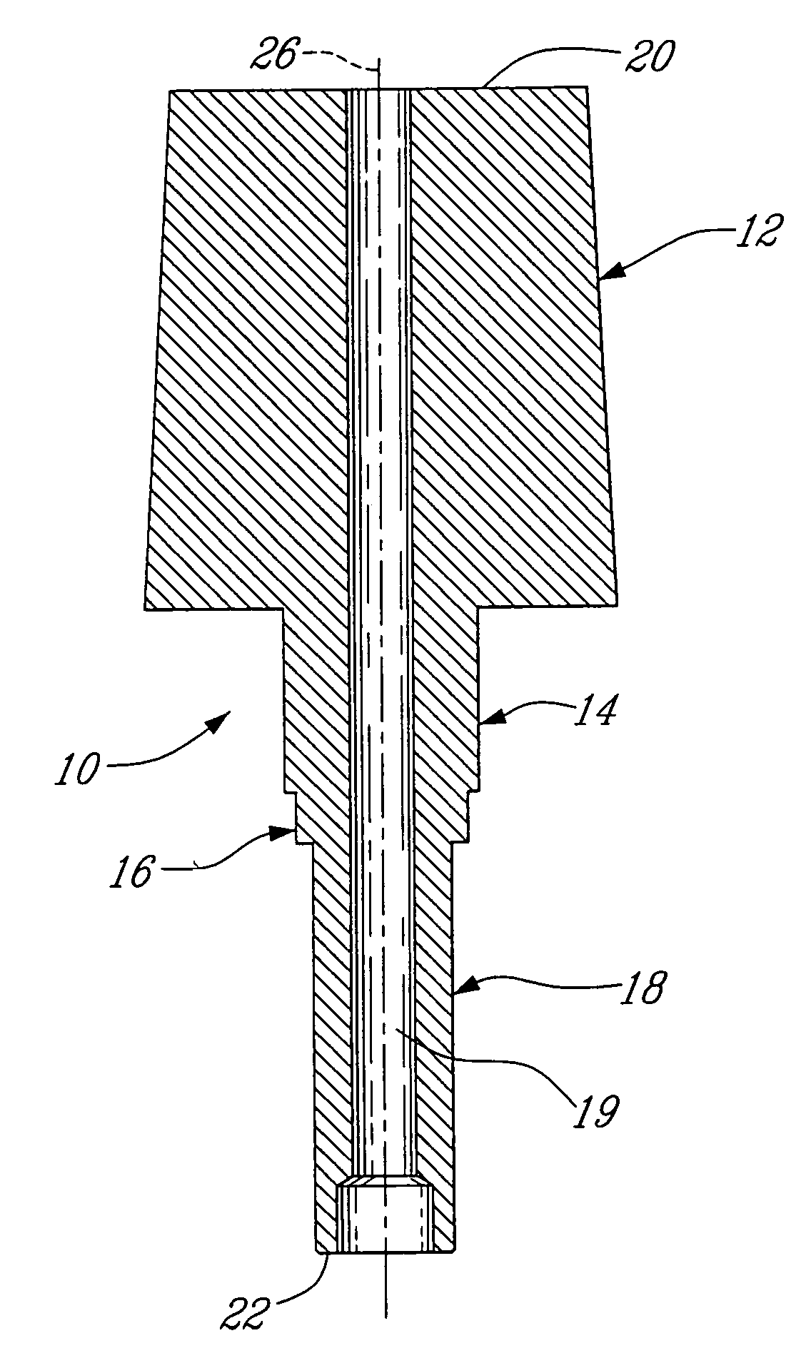
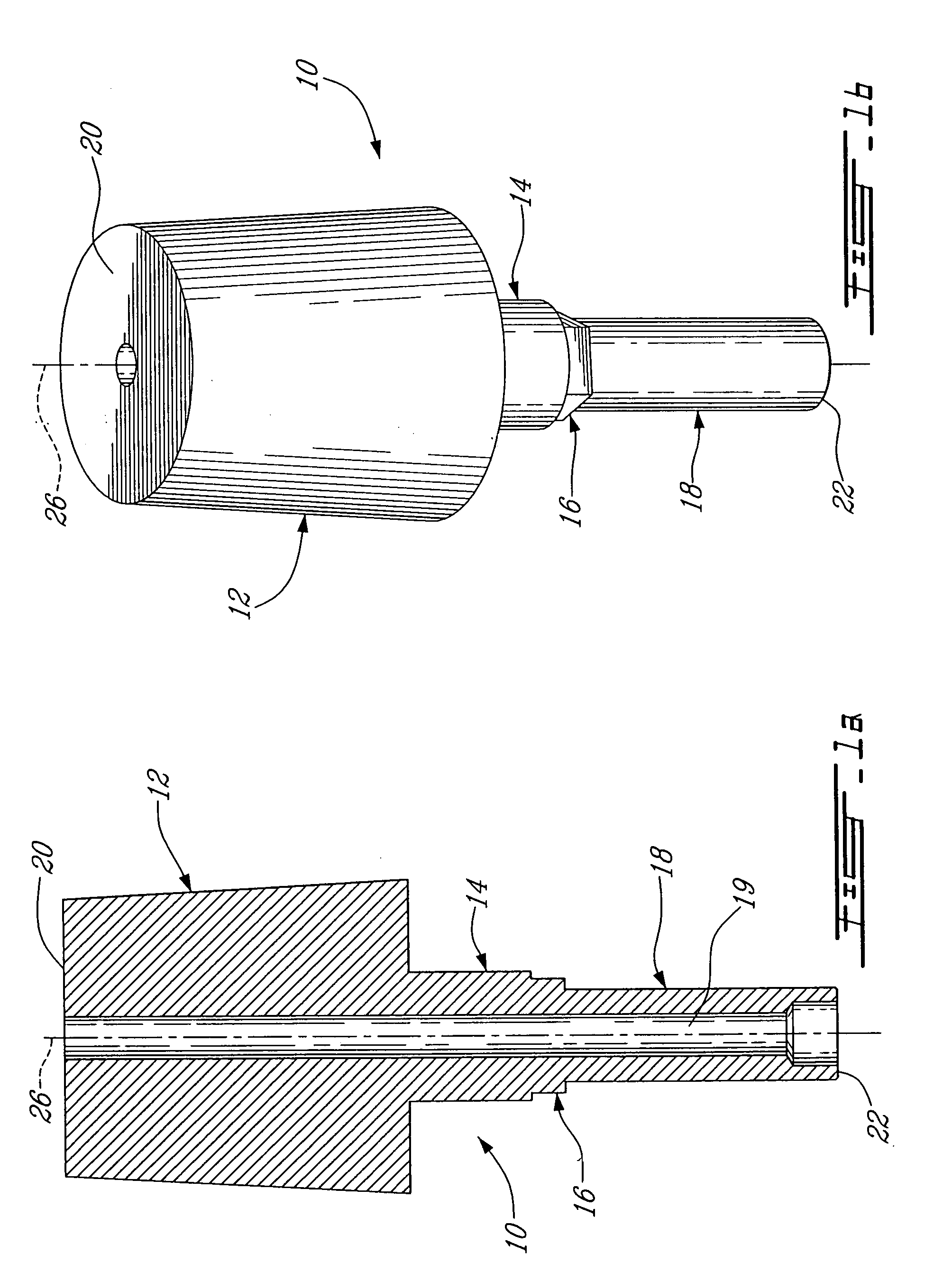
[0079] Turning now more specifically to FIGS. 1a and 1b, the abutment 10 includes an external member defined by an abutment head 12 of a frusto-conical shape, adjacent to a junction segment 14 which is connected to a projection 16 of a substantially polygonal shape. The projection 16 of the abutment 10 is adjacent to an elongated post 18. The abutment head 12, the segment 14, the projection 16 and the post 18 may be integrally made of a single piece of material.

[0080] The abutment 10 includes a central throughbore 19 which spans the entire length of the abutm...

third embodiment

[0139]FIG. 9 of the appended drawings illustrates an implant system 200, according to the present invention. Again, only the differences between the implant system 200 and the implant system described hereinabove with reference to FIGS. 1a to 6b will be described.

[0140] In FIG. 9, the collar member 230 is illustrated has having one of its side higher than the opposite side. This type of implant system or collar member 230 is referred as being contoured. Accordingly the abutment 210, more particularly the abutment head 212 and the junction segment 214, is adapted to fit with the contoured collar member. This type of system may be particularly useful for substantially circular or substantially square teeth, such as a molar, especially when one side of the gum tissue is higher than the opposite side (e.g., lingual v mouth).

fourth embodiment

[0141] An implant system 300, according to the present invention will now be described with reference to FIGS. 10a, 10b and 10c.

[0142] As shown in FIG. 10b, the collar member 330 is contoured as the collar member 230 of FIG. 9. In addition, the collar member 330 and the abutment 310 illustrated in FIGS. 10a, 10b and 10c have a substantially oval shape. Again, the abutment 310, more particularly the abutment head 312 and the junction segment 314, is configured to match the collar member 330. This type of system may be particularly useful for oval teeth, such as a cuspid or bicuspid tooth, especially when one side of the gum tissue is higher than the opposite side (e.g., lingual v mouth). A position that the implant system may held once installed in the mouth of an individual is suggested in FIG. 10a and FIG. 10b where V is the vestibular side, D is the distal side, M is the mouth side and L is the lingual side. Other positions may be assumed depending on the need of the patient.

[01...


PUM


Abstract

The present invention provides an implant system of facilitated use and installation which comprise an implant and a prosthesis support and a method of installation thereof. The prosthesis support disclosed herein includes an abutment and a collar member. Prior art implant systems are mostly made of metallic parts which are assembled with a screw and are shaped to receive a tooth prosthesis. The design of the abutment allows it to be made from highly filled composite materials being of a better optical quality and being easily machinable and further allows its installation without the use of a screwing member. The design of the collar member allows minimization of bacteria growth and tartar formation. The optimization of the implant system proposed herein may reduce stress to the jaw bone and therefore minimize the risk of injury for the patient.

Description

FIELD OF THE INVENTION [0001] The present invention relates to an implant system, a kit and a method of installation thereof. More particularly, the present invention relates to an implant system of facilitated use, assembly and installation. BACKGROUND OF THE INVENTION [0002] It is of general knowledge that the loss of teeth may be compensated by artificial dental implants. A dental implant system typically includes an implant which is inserted firmly into the bone and an abutment which is usually directly or indirectly attached to the implant with a screwing member. The abutment supports the gum tissue and serves as a foundation for the dental prosthesis. The core of the implant is shaped to receive the abutment and an accurate mechanical interconnection is therefore provided between the two components. Such dental implant systems are described, for example, in U.S. Pat. No. 5,810,589, issued Sep, 22, 1998, and U.S. Pat. No. 5,759,036, issued Jun. 2, 1998. More particularly, U.S. ...

Claims


Application Information

Patent Timeline
IPC IPC(8): A61C8/00
CPCA61C8/005A61C8/0054A61C8/006A61C8/0066A61C13/0022
Inventor ENNAJIMI, ELMEKKIKASSEH, ABDESLAMCHAOUKI, JAMALLABBE, GUSTAVO
Owner ENNAJIMI ELMEKKI
Why Eureka
Try Eureka