Balloon catheter with positioning pocket

a balloon catheter and positioning pocket technology, applied in the field of balloon catheters, can solve the problems of loss of muscle tone or tissue integrity, soft tissue damage, etc., and achieve the effect of not causing any injury to soft tissue and not damage to tissu

Active Publication Date: 2005-06-23
CONVATEC TECH INC
View PDF19 Cites 41 Cited by
  • Summary
  • Abstract
  • Description
  • Claims
  • Application Information

AI Technical Summary

Benefits of technology

[0020] The present invention is a medical appliance in the form of a catheter with a balloon carrying distal end formed entirely of soft, compliant material, and therefore incapable of causing any injury to the soft tissue. The rigid portion of a distal end of the appliance, normally needed for insertion, is embodied in a separate element, designed to be withdrawn after introduction of the catheter in the bowel, thus permitting the entire inserted distal end of the catheter to be soft and compliant so that it cannot damage the tissue.

Problems solved by technology

However, having a rigid part within many body organs can cause distention of the tissue, such as sphincter muscles or delicate vessels, resulting in the loss of muscle tone or tissue integrity over time.
Because the Kim catheter, like other bowel management systems of this type, includes a catheter with a distal end having a rigid portion, it can cause soft tissue damage if it remains in the bowel for an extended period of time.
However, the use of a separate rigid introducer element raises the issue of how to attach the element to the distal end of the catheter during insertion and positioning of the catheter within the bowel and thereafter to detach the element from the catheter once the distal end of the catheter is properly positioned, thereby permitting the element to be withdrawn from the body, without causing any soft tissue damage.

Method used


Image

  • Balloon catheter with positioning pocket
  • Balloon catheter with positioning pocket
  • Balloon catheter with positioning pocket

Examples


Embodiment Construction

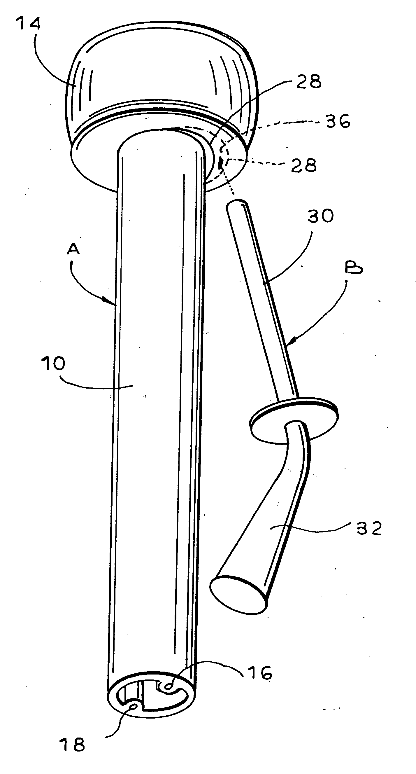
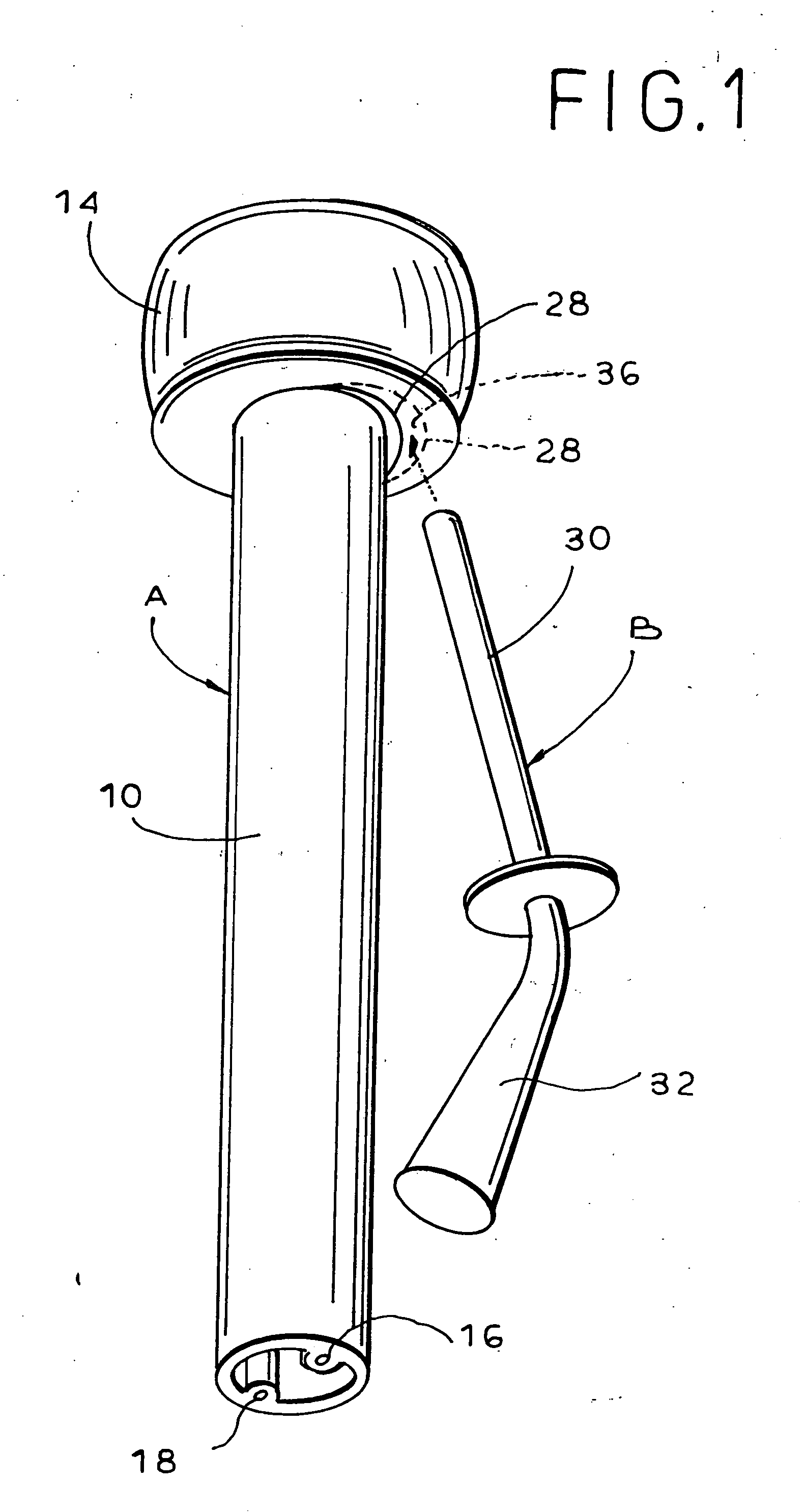
[0044] As is best seen from FIG. 1, the present invention includes a balloon catheter, generally designated A, and a separate introducer element, generally designated B. Catheter A consists of a flexible tube 10 made entirely of soft, compliant material. Tube 10 has a distal end 12 that carries an inflatable balloon 14. Balloon 14 is heat sealed or otherwise affixed to the exterior surface of tube 10. Balloon 14 is also formed entirely from soft, compliant material.

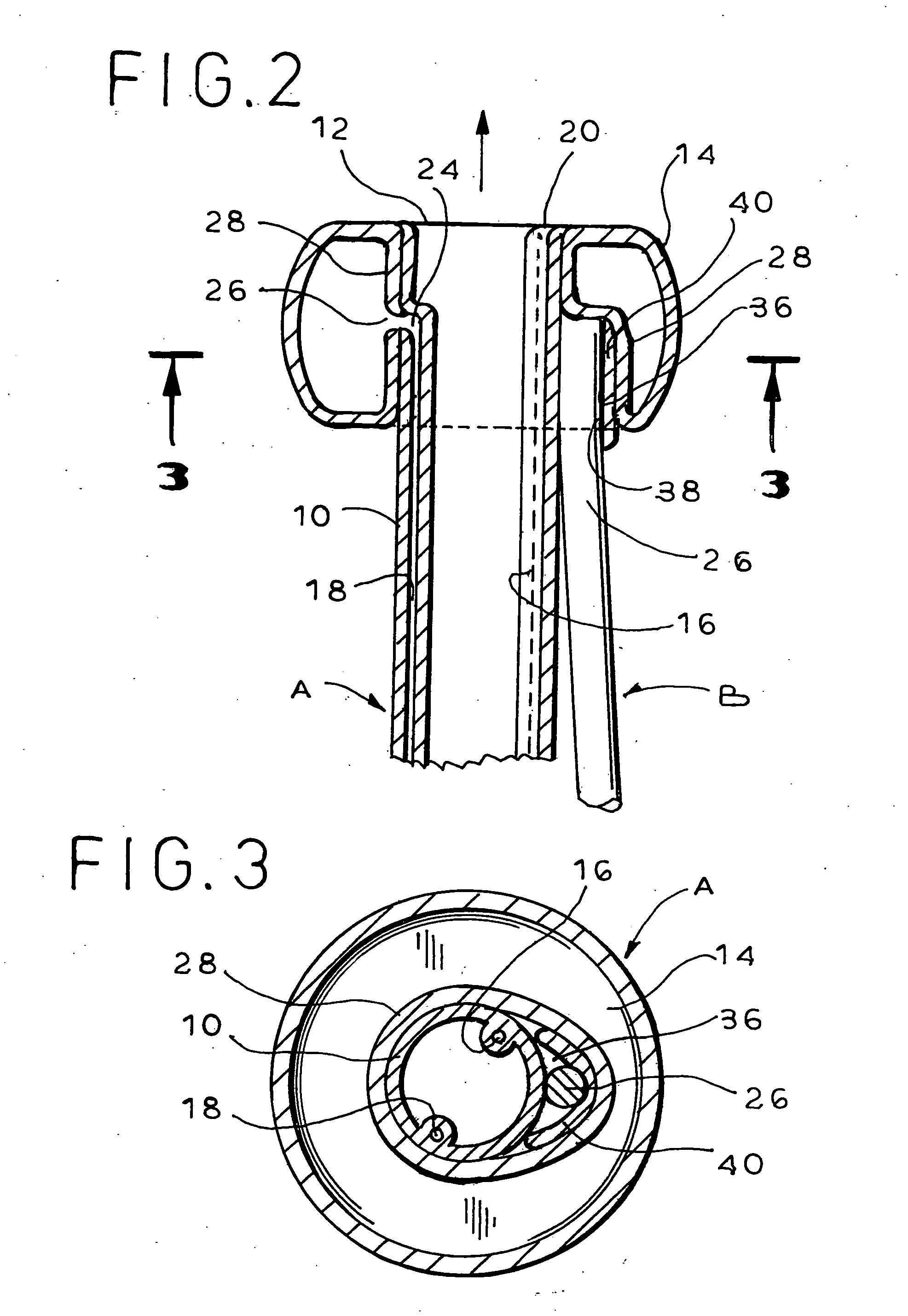
[0045] The interior surface of tube 10 has two integral lumens 16, 18, best seen in FIGS. 2 and 3. The distal end 20 of lumen 16 terminates at the end 12 of tube 10 so as to permit fluid to be introduced into the bowel once the catheter is in position. The distal end 24 of lumen 18 terminates at opening 26 in the wall 28 of balloon 14. The proximal end of lumen 16 (not shown) is attached to a syringe or other source of inflation fluid that is introduced into balloon 14 through lumen 16 to inflate the balloon after the di...


PUM


Abstract

The invention relates to a balloon catheter in which the balloon is mounted on the end of the catheter in a manner that creates a recess or pocket between the catheter wall and balloon wall. The recess or pocket opens toward the proximal end of the catheter. The rigid end of an introducer element or finger is received in the recess to attach it to the catheter. The distal end of the catheter, with the end of the introducer element in the recess, is inserted and positioned within the bowel by manipulating the introducer element or finger. After the catheter is properly positioned in the bowel, the introducer element or finger is withdrawn, detaching it from the catheter as the end of the introducer element slides out of the recess and then out of the bowel. The balloon is inflated prior to or after the withdrawal of the introducer element to anchor the end of the catheter in position within the bowel. Since the distal end of the catheter is made entirely of soft, compliant material, no soft tissue damage can occur from use of the device, even when the catheter remains in place within the body over an extended time period.

Description

CROSS-REFERENCE TO RELATED APPLICATIONS [0001] Not Applicable STATEMENT REGARDING FEDERALLY SPONSORED RESEARCH OR DEVELOPMENT [0002] Not Applicable REFERENCE TO A “SEQUENCE LISTING”, A TABLE, OR A COMPUTER PROGRAM LISTING APPENDIX SUBMITTED ON COMPACT DISC [0003] Not Applicable BACKGROUND OF THE INVENTION [0004] 1. Field of the Invention [0005] The present invention relates to a balloon catheter designed to be introduced into a body cavity, and more particularly to a balloon catheter including a recess or pocket adapted to receive the end of a separate withdrawable rigid element or finger to aid in the introduction and positioning of the balloon carrying catheter end within a body cavity. [0006] 2. DESCRIPTION OF PRIOR ART INCLUDING INFORMATION DISCLOSED UNDER 37 CFR 1.97 AND 1.98 [0007] Annular inflatable balloons surrounding the distal end of catheters have been used for many years to retain the distal end of a catheter in position in anatomical organs. Such catheters are commonly...

Claims


Application Information

Patent Timeline
Patent Type & Authority Applications(United States)
IPC IPC(8): A61F2/00A61M25/00A61F2/958A61M25/01
CPCA61M25/01A61M25/0102A61M25/04
Inventor MACHADO, FIDELISGREGORY, CHRISTOPHER
Owner CONVATEC TECH INC
Why Eureka
Try Eureka