

Piston for a syringe and a prefilled syringe using the same
a syringe and pre-filled technology, applied in the field of syringes and pre-filled syringes, can solve the problems of reducing the production cost of syringes, and avoiding the reuse of syringes. the effect of increasing the production cos
- Summary
- Abstract
- Description
- Claims
- Application Information
AI Technical Summary
Benefits of technology
Problems solved by technology
Method used
Image

Examples
Embodiment Construction
[0015] We, the inventors have made various efforts to impart a reuse-preventive mechanism to a prefilled syringe and consequently, have found that the reuse-preventive device can ecconomically be given to the syringe by composing a stopper for a prefilled syringe to have a backstop function. The present invention is based on this finding. That is, the present invention has the following constructive features:
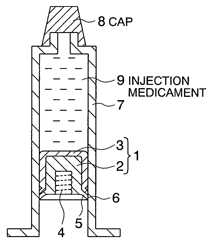
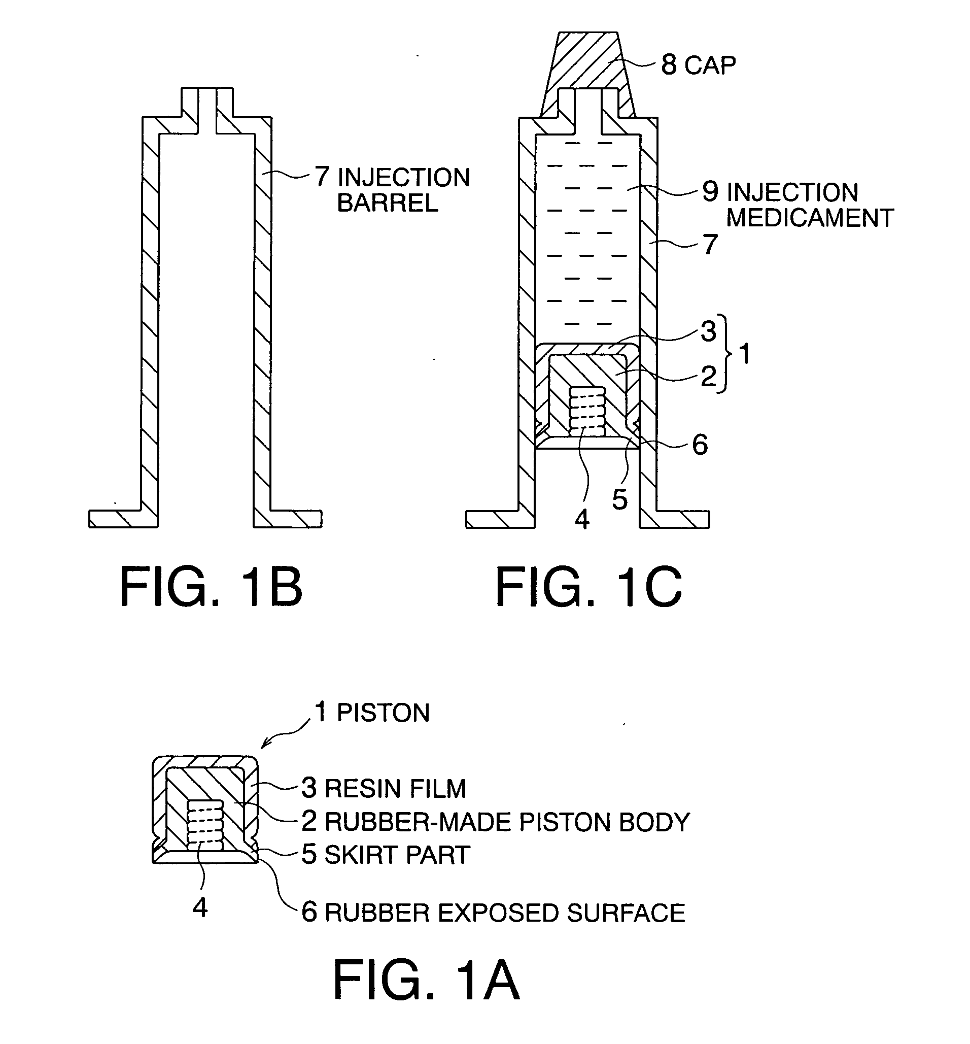
[0016] (1) Apiston for a syringe for sealing an injection barrel filled with a medicament comprising a skirt part capable of serving as a backstop device.
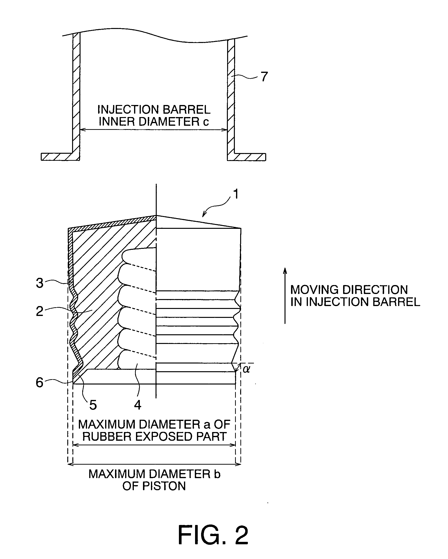
[0017] (2) The piston for a syringe as described in (1), wherein the piston is subjected to film lamination and / or lubricant coating, the skirt part has a rubber exposed surface on a contact surface with the injection barrel and at least a part of the rubber exposed surface is inside the maximum outer diameter of the stopper and outside the inner diameter of the injection barrel.
[0018] (3) The piston for a syringe as describ...
PUM
 Abstract
Description
Claims
Application Information