
Prosthetic foot with rocker member

a technology of prosthetic feet and rockers, applied in the field of lower limb prostheses, can solve the problems of less efficient energy storage and release during motion of the foot, difficult to wholly contain in a cosmesis, bulky foot designs, etc., and achieves the effect of increasing the roll-up effect, facilitating the initial roll-up of the rocker member, and facilitating the introduction into and removal

Inactive Publication Date: 2005-06-23
GRAMTEC INNOVATION +1
View PDF26 Cites 150 Cited by
  • Summary
  • Abstract
  • Description
  • Claims
  • Application Information

AI Technical Summary

Benefits of technology

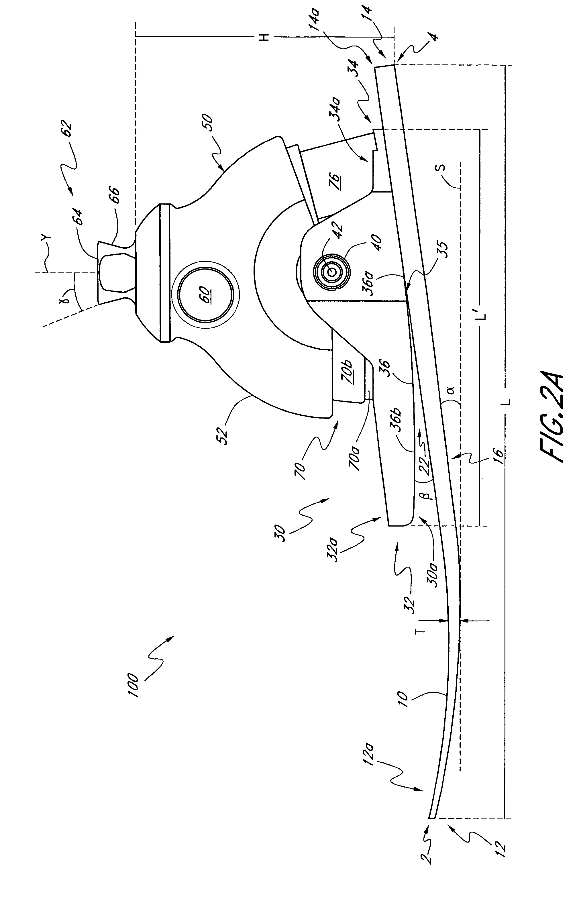
[0011] In at least one embodiment, the prosthetic foot is configured to provide an improved fluid transition between heel-strike and toe-off. The foot has a rocker member having an anterior section and a posterior section, wherein the anterior section is elongated in shape. The rocker member is preferably removably connected in cantilever fashion at the posterior section thereof to a foot member, wherein the foot member has a toe section and a heel section. In one embodiment, the posterior section of the rocker member has a generally planar lower surface, whereas the anterior section has a generally curved lower surface. In another embodiment, the front and posterior sections of the rocker member have generally planar lower surfaces.
[0012] As the foot transitions from heel-strike to toe-off, flexion of the foot member increases and the rocker member gradually rolls-up onto the foot member. This roll-up effect advantageously adjusts the stiffness of the foot to the load being applied. The greater the applied load, the more the rocker member rolls-up onto the foot member, and the greater the increase in the flexion and stiffness of the foot member. The stiffness of the foot member can also be varied based on the location along the foot member where the rocker member is connected. The further the rocker member is connected from the heel of the foot member, the greater the increase in stiffness during roll-up of the rocker member onto the foot member.
[0014] In another preferred embodiment, the anterior section of the rocker member is advantageously tapered for easier introduction into and removal from a cosmesis. Similarly, the posterior section of the rocker member can also be tapered. Moreover, the foot blade can also be tapered at the heel section thereof to facilitate the initial roll-up of the rocker member onto the foot member. Also, the length of the anterior section of the rocker member can be advantageously varied to provide an increased roll-up effect. In another embodiment, the anterior section can have a recessed or indented surface to decrease the weight of the rocker member.
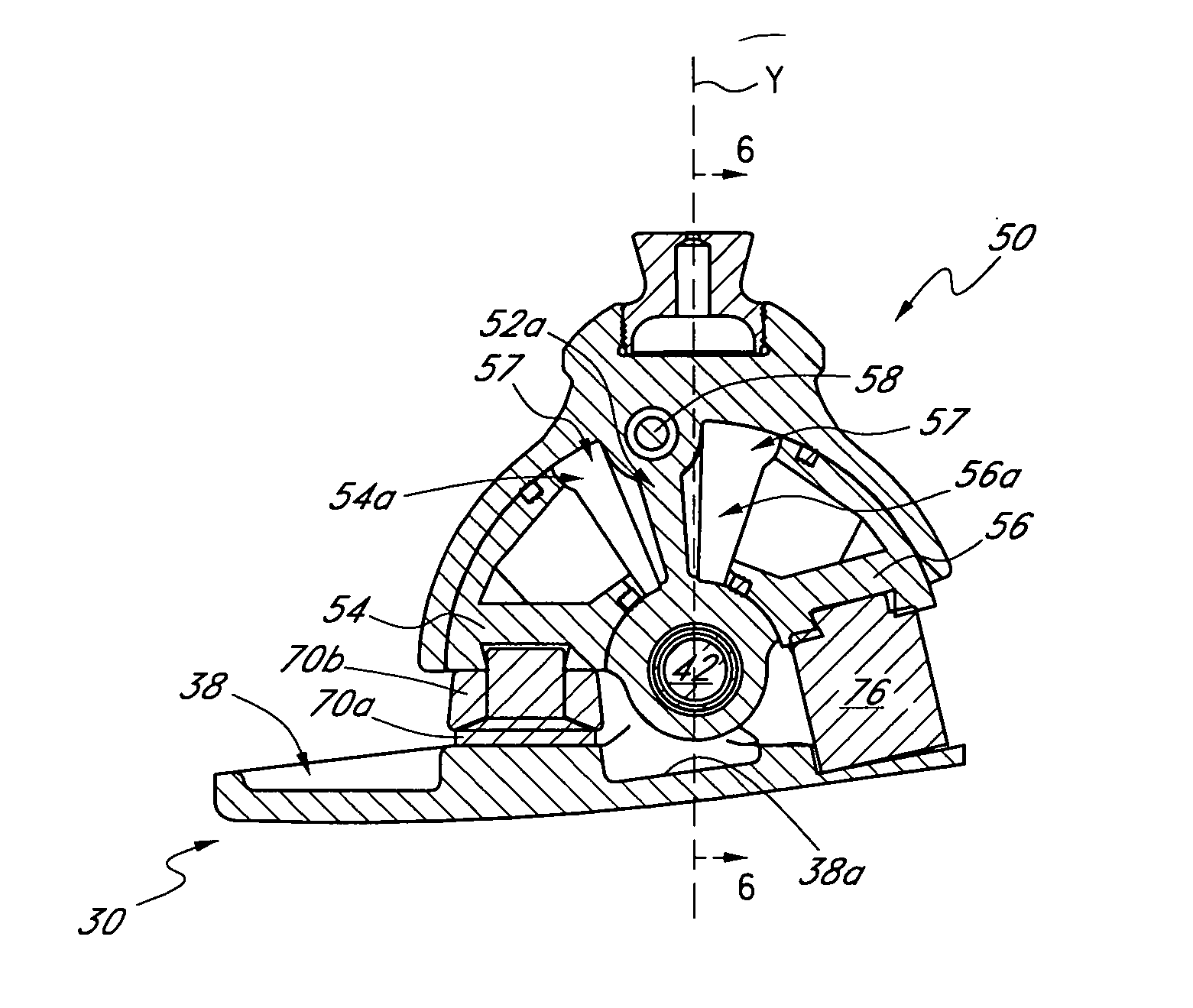
[0015] In some embodiments, the prosthetic foot also comprises an ankle module having an anterior portion and a posterior portion, the module movably connected to the rocker member about an axis. Bumpers can be disposed between the ankle module and rocker member to provide energy storage and release during foot motion. Preferably, at least one of the bumpers is made of compressible material. Optionally, at least one of the bumpers can be made of a rigid or semi-rigid material. More preferably, at least a portion of the bumpers is compressible. In one embodiment, the bumpers are advantageously configured to reduce any clicking or other noise generated during the transition from heel-strike to toe-off of the foot. For example, at least one of the bumpers can be configured to function as a muffler or damper.

Problems solved by technology

However, such foot designs tend to be bulky and may be difficult to wholly contain in a cosmesis.
Additionally, in some instances, the efficiency of the springs may deteriorate following prolonged use, resulting in less efficient energy storage and release during motion of the foot.
However, such designs also have disadvantages.
Additionally, existing prosthetic foot designs do not provide the desired degree of stride fluidity during foot motion.
For example, existing designs do not adequately adapt the degree of flexion of the foot based on the load being applied to the foot.
Some existing designs are difficult to fit into and remove from a cosmesis.

Method used


Image

  • Prosthetic foot with rocker member
  • Prosthetic foot with rocker member
  • Prosthetic foot with rocker member

Examples


Embodiment Construction

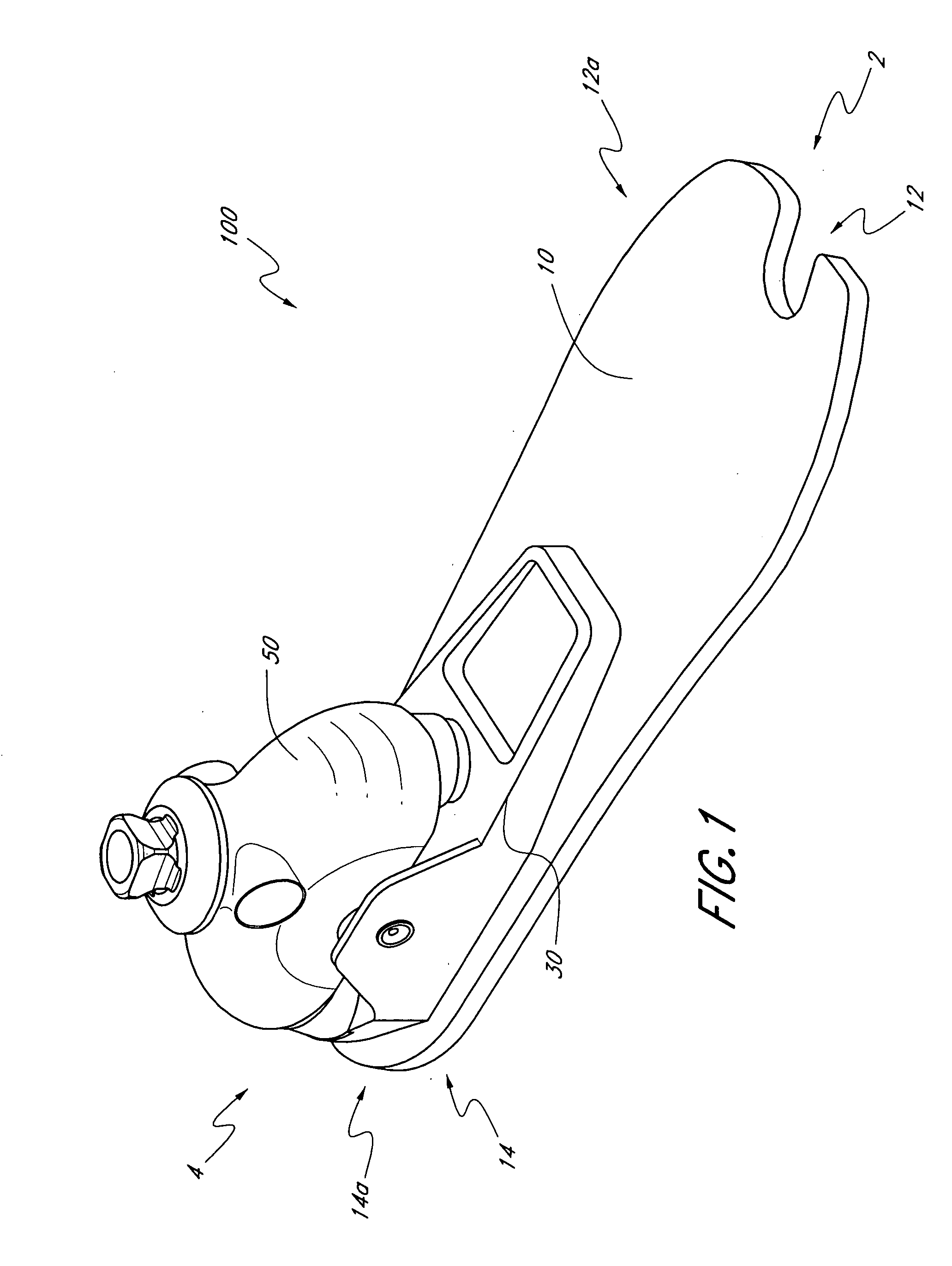
[0031]FIGS. 1-2A illustrate one embodiment for a prosthetic foot 100 extending between a toe section 2 and a heel section 4. Preferably, the prosthetic foot 100 comprises a foot member or support 10 which may have an elongate configuration having a length L extending between a front end 12 and a rear end 14. As used herein, length L refers to the horizontal length of the foot member 10 along a plane parallel to a support surface S on which the prosthetic foot 100 rests. Preferably, the length L can be between about 18 and 40 cm, corresponding to the size of the prosthetic foot 100, when the foot 100 has a neutral heel height position, as described below. In one embodiment, the length L is about 25 cm. However, the length L can have other values and can vary as the heel height position of the prosthetic foot 100 is adjusted. The foot member 10 also preferably comprises an anterior portion 12a, a posterior portion 14a, and an intermediate portion 16. In one embodiment, the anterior po...


PUM


Abstract

A prosthetic foot comprises a foot member, a rocker member connected in cantilever fashion to the foot member, and an ankle module movably connected to the rocker member about an axis, wherein an anterior section of the rocker member is configured to roll-up onto the foot member an amount corresponding to the load applied on the foot, and wherein the foot member is configured to facilitate the initial roll-up of the rocker member.

Description

BACKGROUND OF THE INVENTION [0001] 1. Field of the Invention [0002] The present invention relates in one embodiment to lower limb prostheses in general, and, in particular, to a prosthetic foot having an ankle section with a rocker member connected to a foot member, where the rocker member facilitates the flexion of the foot member. [0003] 2. Description of the Related Art [0004] Prosthetic feet of different designs are well known in the art. The various conventional designs have sought to solve various limitations associated with prosthetic feet. [0005] Common to many conventional prosthetic foot designs is the desire to approximate the feel and fluid range of motion of a human foot's natural stride. One aspect of said natural stride is the ability to fluidly transition from heel-strike to toe-off during motion of the foot. [0006] Some conventional designs attempt to provide said fluid transition by incorporating springs to store and release energy during motion of the prosthetic f...

Claims


Application Information

Patent Timeline
IPC IPC(8): A61F2/00A61F2/50A61F2/66A61F2/74
CPCA61F2/66A61F2/6607A61F2002/30359A61F2002/30467A61F2002/5006A61F2002/5007A61F2220/0083A61F2002/6621A61F2002/6642A61F2002/6671A61F2002/745A61F2002/748A61F2220/0033A61F2002/5055A61F2/748A61F2/74
Inventor GRAMNAS, FINNRAGNARSDOTTIR, HEIDRUN GIGJAASGEIRSSON, SIGURDUR
Owner GRAMTEC INNOVATION
Learn More