Line-of-sight guiding degree calculation system and line-of-sight guiding degree calculation program as well as line-of-sight guiding degree calculation method

Inactive Publication Date: 2005-06-23
SEIKO EPSON CORP
View PDF10 Cites 5 Cited by
  • Summary
  • Abstract
  • Description
  • Claims
  • Application Information

AI Technical Summary

Benefits of technology

[0237] Consequently, an advantage equivalent to that in the line-of-sight guid

Problems solved by technology

However, in related art documents JP-A-2002-175290 and JP-A-6-162, since the apparatus is constituted to detect an eye flow using a device such as an eye camera, there is a problem in that a size of the apparatus increases and a large amount of cost is required.
Thus, it is likely that an eye flow at the time when others look at the layout result for the first time and an eye flow of the designer that is actually detected are inconsistent.
Therefore, there is a problem in that, even if the designer carries out layout while detecting an eye flow of the designe

Method used


Image

  • Line-of-sight guiding degree calculation system and line-of-sight guiding degree calculation program as well as line-of-sight guiding degree calculation method
  • Line-of-sight guiding degree calculation system and line-of-sight guiding degree calculation program as well as line-of-sight guiding degree calculation method
  • Line-of-sight guiding degree calculation system and line-of-sight guiding degree calculation program as well as line-of-sight guiding degree calculation method

Examples


first exemplary embodiment

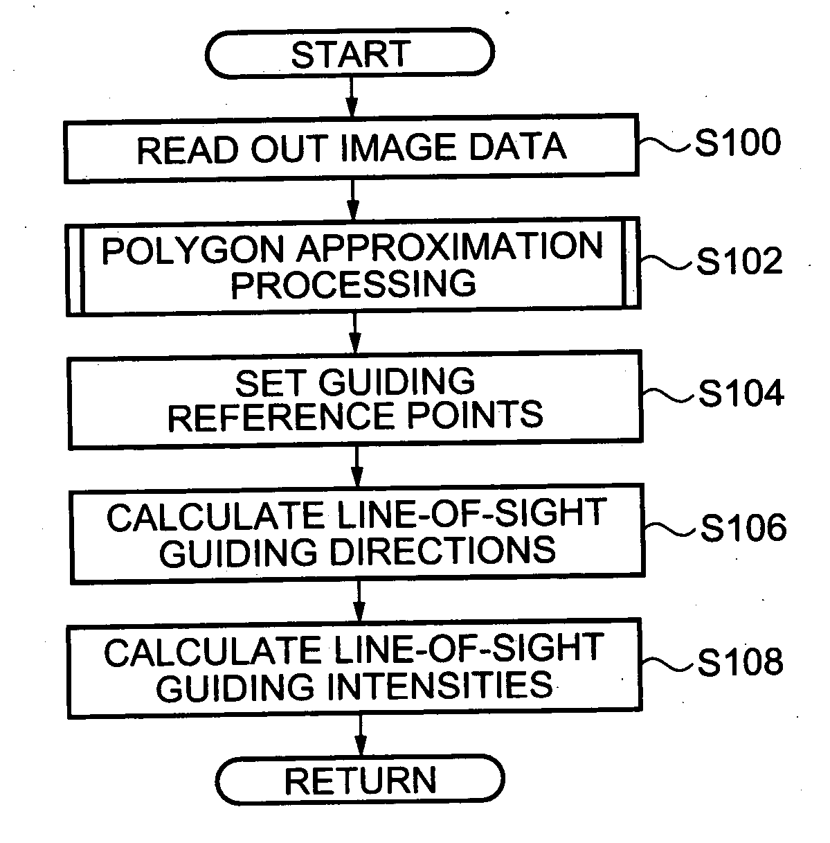
[0339] A first exemplary embodiment of the invention will be hereinafter explained with reference to the drawings. FIGS. 1 to 22 are diagrams showing a first exemplary embodiment of a line-of-sight guiding degree calculation system and a line-of-sight guiding degree calculation program as well as a line-of-sight guiding degree calculation method in accordance with the exemplary embodiments.

[0340] In this exemplary embodiment, the line-of-sight guiding degree calculation system and the line-of-sight guiding degree calculation program as well as the line-of-sight guiding degree calculation method in accordance with the embodiments are applied to a case in which directions in which an image object guides a line-of-sight and intensities at which the image object guides the line-of-sight are calculated.

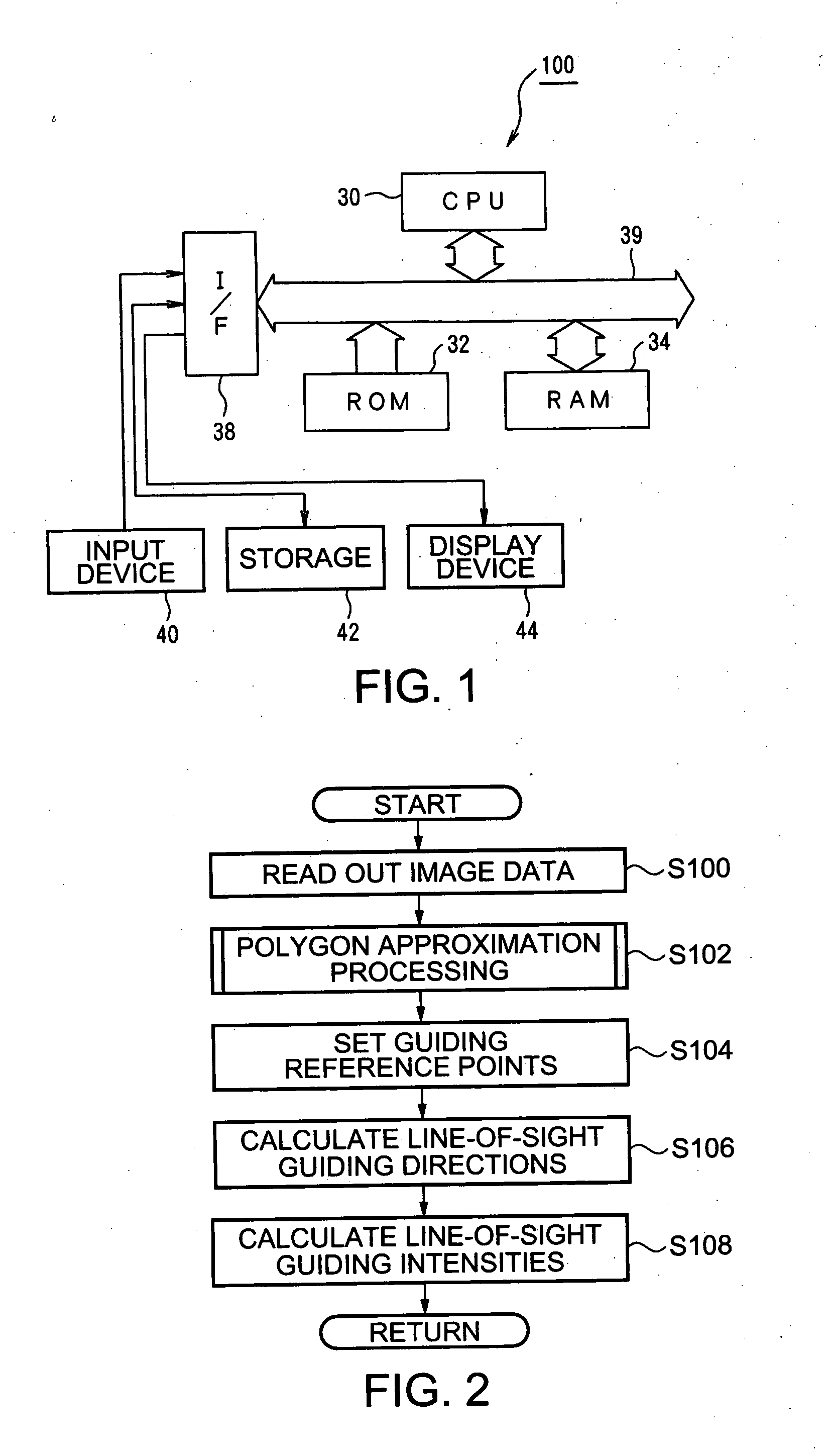
[0341] First, a structure of a layout apparatus 100, to which the invention is applied, will be explained with reference to FIG. 1.

[0342]FIG. 1 is a schematic block diagram showing the ...

second exemplary embodiment

[0428] Next, a second exemplary embodiment of the invention will be explained with reference to the drawings. FIGS. 23 to 26 are diagrams showing a second exemplary embodiment of the line-of-sight guiding degree calculation system and the line-of-sight guiding degree calculation program as well as the line-of-sight calculation method in accordance with the invention.

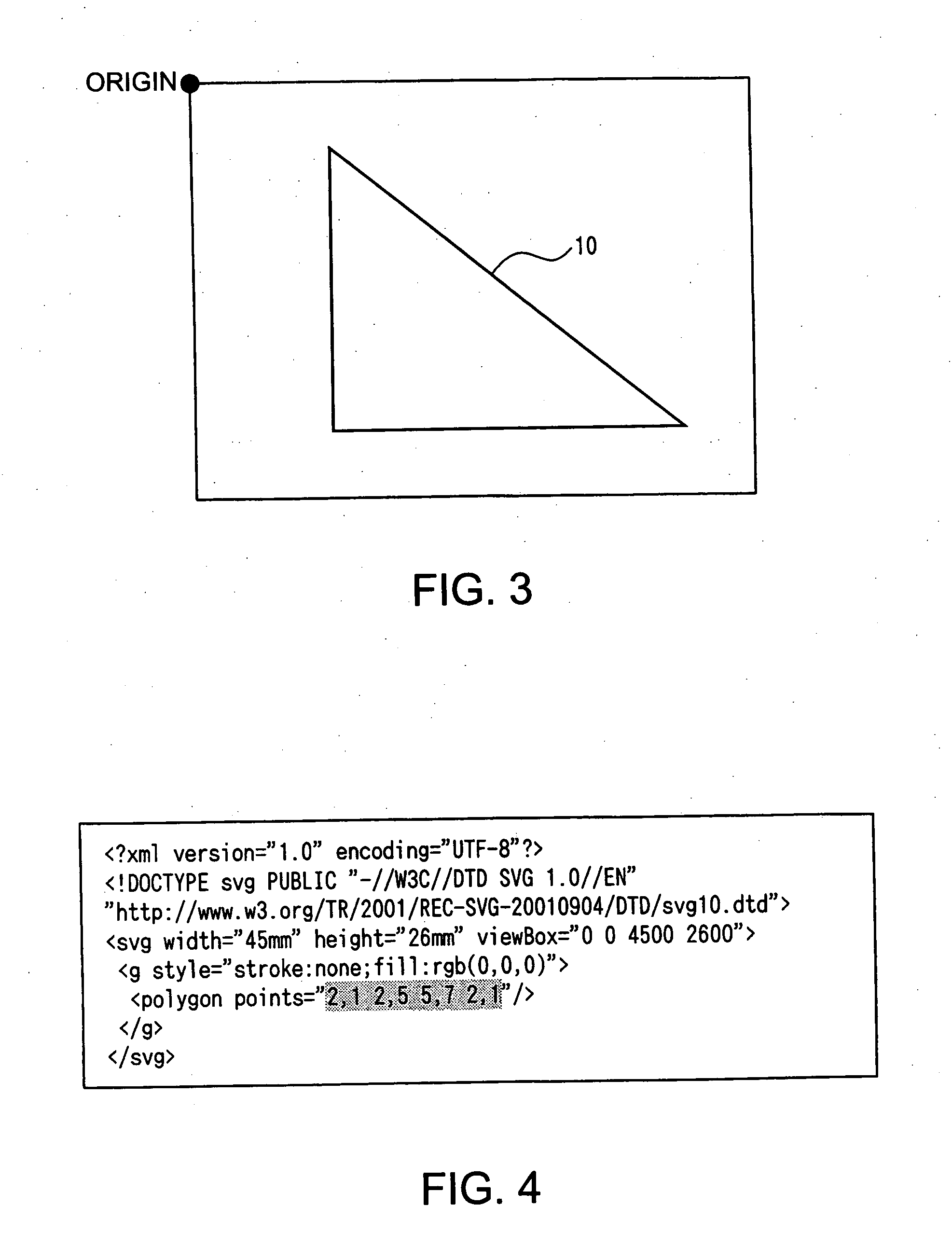
[0429] In this exemplary embodiment, the line-of-sight guiding degree calculation system and the line-of-sight guiding degree calculation program as well as the line-of-sight calculation method in accordance with the exemplary embodiment are applied to a case in which a direction in which the image object 10 guides a line-of-sight and an intensity at which the image object 10 guides the line-of-sight. This exemplary embodiment is different from the first exemplary embodiment in that distances from sides opposed to guiding reference points (hereinafter referred to as opposed sides) of the contour line of the image object...

third exemplary embodiment

[0451] A third exemplary embodiment of the invention will be hereinafter explained with reference to the drawings. FIGS. 27 to 30 are schematic diagrams showing a third exemplary embodiment of the line-of-sight guiding degree calculation system and the line-of-sight guiding degree calculation program as well as the line-of-sight calculation method in accordance with the exemplary embodiment.

[0452] In this exemplary embodiment, the line-of-sight guiding degree calculation system and the line-of-sight guiding degree calculation program as well as the line-of-sight calculation method in accordance with the invention are applied to a case in which a direction in which an image object guides a line-of-sight and an intensity at which the image object guides the line-of-sight. This exemplary embodiment is different from the first exemplary embodiment in that judgment processing judging whether approximation processing is to be performed is performed on the basis of the number of image obj...


PUM


Abstract

Exemplary embodiments provide a line-of-sight guiding degree calculation system that can realize reduction in size and reduction in cost of an apparatus and can obtain an appropriate eye flow surely. First, a layout apparatus approximates an image object to a polygon on the basis of vector image data and detects respective apexes of the approximated image object as guiding reference points. Then, for each of the guiding reference points, the layout apparatus forms two auxiliary lines crossing the guiding reference point imaginarily along a contour of the image object and calculates a direction in which a bisector of an obtuse angle among angles formed by the imaginary auxiliary lines extends outward from the guiding reference point as a line-of-sight guiding direction. In addition, for each of the guiding reference points, the layout apparatus calculates a distance from a center of gravity G of the image object to the guiding reference point as a line-of-sight guiding intensity. Consequently, it can be calculated quantitatively and appropriately in which direction the image object tends to guide a line-of-sight.

Description

BACKGROUND OF THE INVENTION [0001] 1. Field of Invention [0002] Exemplary embodiments of the present invention relate to a system and a program as well as a method to calculate a degree at which an image guides a line-of-sight. Exemplary embodiments further relate to a line-of-sight guiding degree calculation system and a line-of-sight guiding degree calculation program as well as a line-of-sight guiding degree calculation method that can realize reduction in size and reduction in cost of an apparatus and can obtain an appropriate eye flow. [0003] 2. Description of Related Art [0004] A document with a high design property, in which layout elements (e.g., a title, an image, and a text) are laid out so as to be easily seen, such as a catalogue or the like for products, is called a visual document. Since creation of a visual document requires a lot of design know-how, it is difficult for a general businessperson to create a visual document. Therefore, creation of a visual document is o...

Claims


Application Information

Patent Timeline
IPC IPC(8): A61B3/113G06F17/00G06T11/60
CPCG06T11/60
Inventor KAYAHARA, NAOKINAGAHARA, ATSUSHI
Owner SEIKO EPSON CORP
Why Eureka
Try Eureka