Method and apparatus for micro-contact printing

a micro-contact printing and printing method technology, applied in biochemistry apparatuses, biochemistry apparatus and processes, nanotechnology, etc., can solve the problems of micro-contact printing, inability to achieve reliable contact between stamp surface pattern elements and substrates, and pattern distortions of unacceptable magnitud

Inactive Publication Date: 2005-06-30
AXELA
View PDF12 Cites 24 Cited by
  • Summary
  • Abstract
  • Description
  • Claims
  • Application Information

AI Technical Summary

Benefits of technology

[0011] biasing means communicating with an inner surface of the flexible diaphragm portion through the fluid flow passageway for biasing the flexible diaphragm portion out...

Problems solved by technology

Current methods of micro-contact printing pose several challenges.
One primary difficulty is the need to achieve reliable contact between the stamp surface pattern elements and the substrate.
However, this method has the disadvantage of either requiring very accurate positional control or of compressing the stamp and thereby creating pattern distortions of unacceptable magnitude including the possibility of establishing contact between the substrate and areas of the stamp between the raised features.
These methods mitigate the contact issue in that they decrease the required precision of the motion control.
The use of a pneumatic or hydraulic coupling eases the required adjustments, but still presents problems of friction and control.
Force feedback to the motion control device allows rapid, controllable adjustment tha...

Method used


Image

  • Method and apparatus for micro-contact printing
  • Method and apparatus for micro-contact printing
  • Method and apparatus for micro-contact printing

Examples


Embodiment Construction

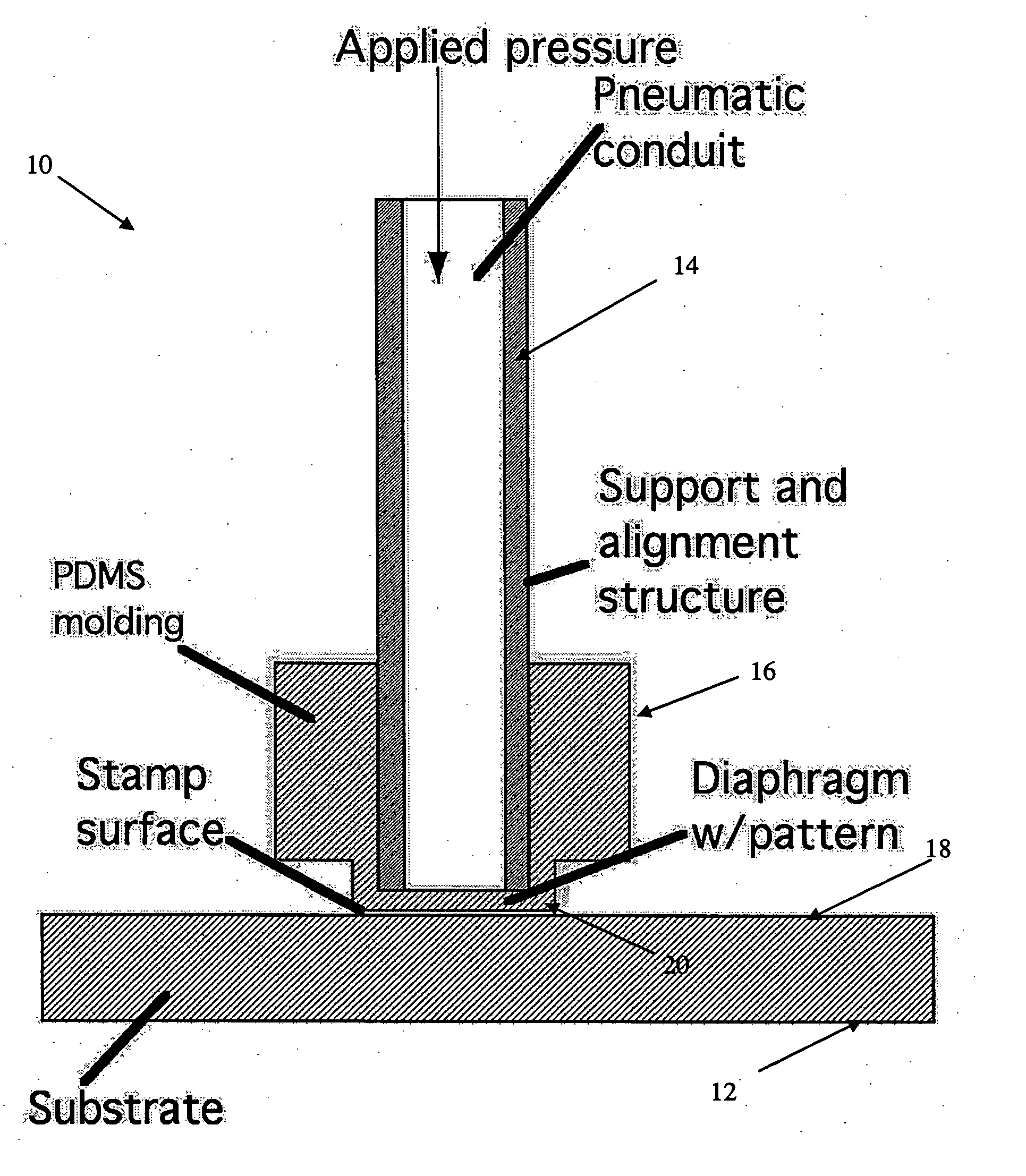
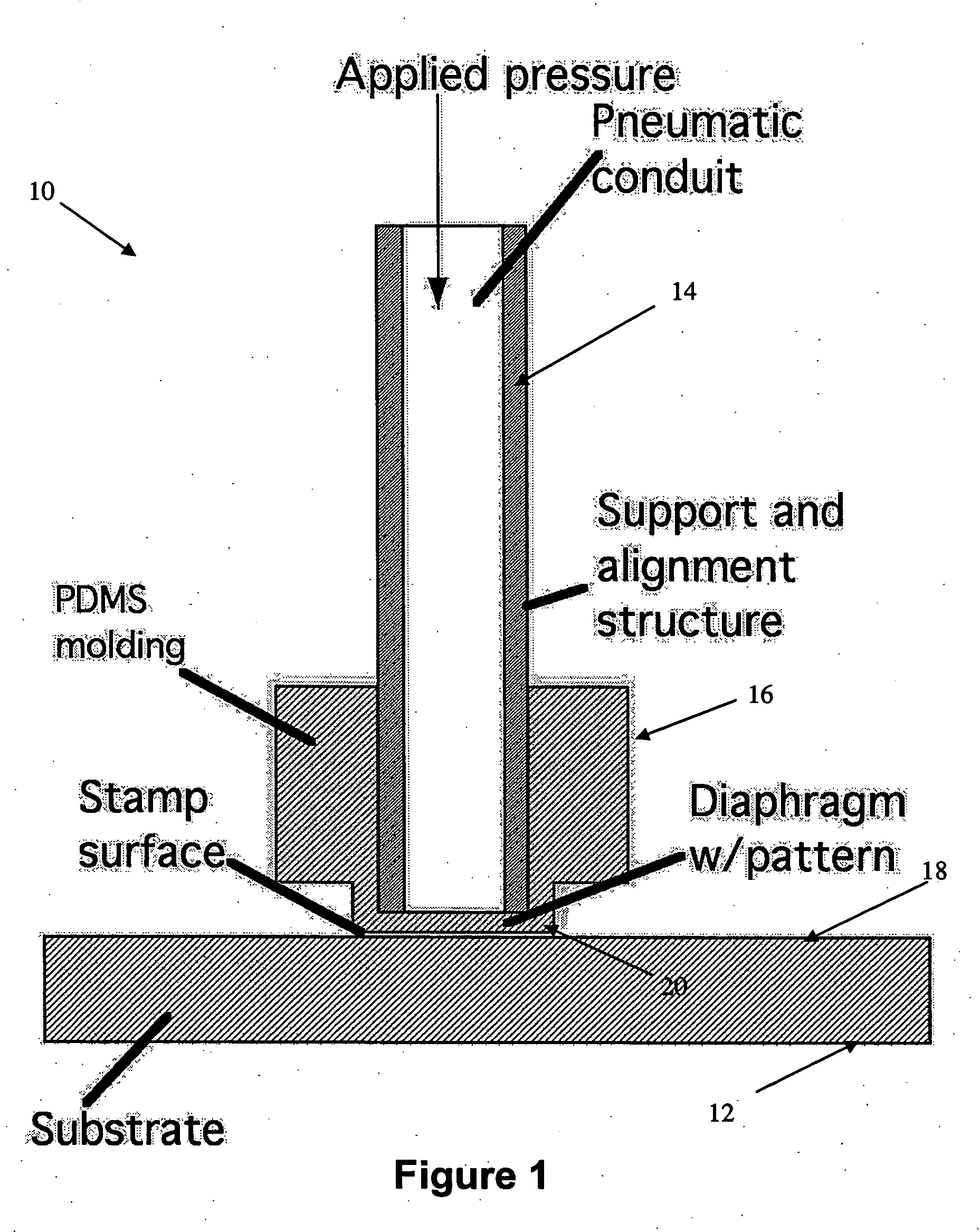
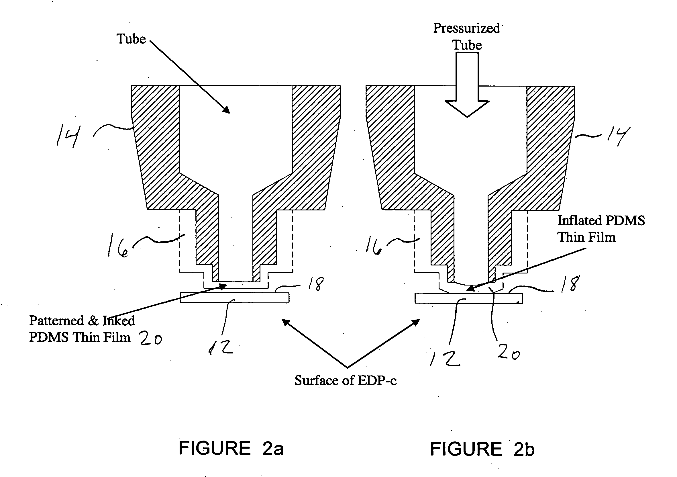
[0019] The present invention allows for highly uniform contact between a stamp containing surface pattern elements and substrate while requiring only relatively coarse positioning of the stamp and substrate. FIG. 1 is a sectional view of a stamp integral with a support and alignment structure shown generally at 10 engaging a substrate 12 to be printed with a pattern. Stamp 10 includes a rigid structural support and alignment member 14, the cylindrical tubular member shown in FIG. 1 is a preferred embodiment but it will be appreciated that the member 14 need not be a cylindrical tube per se. Located over one end of tubular member 14 is a polydimethylsiloxane (PDMS) micro-contact printing stamp 16 used to transfer the pattern to the top surface 18 of substrate 12.

[0020] The PDMS micro-contact printing stamp 16 includes a diaphragm portion 20 which fits over the end of tubular member 14 which is thin enough to be able to undergo displacement in the vertical direction. Typical dimensio...


PUM


Abstract

The present invention provides an apparatus for producing patterns on a surface of a substrate. The apparatus includes a rigid support member such as a rigid tubular structure having first and second opposed ends and a fluid flow passageway extending therethrough. A printing stamp is attached at one of the opposed ends of the rigid support member. The printing stamp has a flexible diaphragm portion which has an outer surface which is coated with one or more materials in a pre-selected pattern. A pneumatic pressurizing mechanism communicating with an inner surface of the flexible diaphragm portion through the fluid flow passageway is used to bias the flexible diaphragm portion outwardly into intimate and substantially uniform contact with the surface of the substrate for transferring the pre-selected pattern onto said surface. The rigid tubular supports are attached to a robotic positioning mechanism for providing control of positioning of the stamp relative to the substrate surface.

Description

FIELD OF THE INVENTION [0001] The present invention relates to a method and apparatus for the production of micro patterns on various substrates. BACKGROUND OF THE INVENTION [0002] Microcontact printing is a technique of patterning structures on a surface by using an elastomeric stamp with relief patterns. The stamp is inked with the material to be patterned then put in contact with the surface and transfer of the the ink only occurs in the areas of the relief that come in contact with the surface. [0003] Current methods of micro-contact printing pose several challenges. One primary difficulty is the need to achieve reliable contact between the stamp surface pattern elements and the substrate. As the “ink” being transferred is essentially a molecular monolayer, it is essential that the stamp (typically made from a polymer such as polydimethylsiloxane (PDMS)) come into intimate contact with the substrate. This can be accomplished in a number of ways. The stamp surface may be taken to...

Claims


Application Information

Patent Timeline
IPC IPC(8): B41F17/00B41K1/28G03F7/00
CPCB41F17/006B41K1/28G03F7/0002B82Y40/00B82Y10/00B41F17/00B41K1/00
Inventor CRACAUER, RAYMOND FRANCISGANSKE, ROCKYGOH, M. CYNTHIAGOH, JANE B.LIEDERMAN, ADAM BRIANLOO, RICHARDTAM, PUI
Owner AXELA
Why Eureka
Try Eureka