Method, apparatus and adhesive composition for ophthalmic lens blocking

a technology of ophthalmic lenses and adhesive compositions, applied in the direction of graft polymer adhesives, polyureas/polyurethane adhesives, domestic applications, etc., can solve the problems of dispersion, wax itself is rather messy, and the time required for setting is quite significan

Inactive Publication Date: 2005-06-30
MICRO OPTICS DESIGN
View PDF19 Cites 38 Cited by
  • Summary
  • Abstract
  • Description
  • Claims
  • Application Information

AI Technical Summary

Benefits of technology

[0023] (v) the adhesive being selected to have a dimensional change on setting low enough to be capable of setting in less than 30 seconds without imparting undue stresses on the lens blank and capable of total adhesive failure without lens or lens blank damage or leaving residue on the lens upon application of a sufficient stripping force acting between the lens blank and the lens block.
[0044] The adhesive should be selected to be capable of total adhesive failure without lens or lens block damage or leaving residue on the lens upon application of a sufficient stripping force acting between the lens and the lens block.
[0053] The safety sensor may further communicate with the controller with the controller causing the motion of the transporter to be interrupted.

Problems solved by technology

The wax can cause contamination of the lens, the heat associated with the wax may cause distortion problems with the lens, the wax itself tends to be rather messy and the time required for setting is quite significant, on the order of 15 minutes, before the lens can be safely released to subsequent processing operations.
Other bonding agents, such as curable adhesives have been proposed for bonding a lens to a lens block however these generally present their own disadvantages.
The formulation however has a significant amount of shrinkage requiring relatively slow curing times so as not to impart undue stresses on the lens which may cause lens deflection and subsequent optical errors.
The use of the compounds taught by this patent would be prohibitively slow in de-blocking were a bond to be effected over the entire lens surface.
Many of the formulations taught use water as the de-blocking solvent which may not be desirable where water-based lubricants are used in the surfacing operation.
Furthermore the use of dots does not provide the degree of support that will be provided by an even layer of UV cement between the lens and the lens block.
This may be problematic in cases where a lens is to be blocked which has poor UV transmitting properties such as a UV blocking lens.
Furthermore, no apparatus is taught for how accurate blocking may be carried out.

Method used


Image

  • Method, apparatus and adhesive composition for ophthalmic lens blocking
  • Method, apparatus and adhesive composition for ophthalmic lens blocking
  • Method, apparatus and adhesive composition for ophthalmic lens blocking

Examples


Embodiment Construction

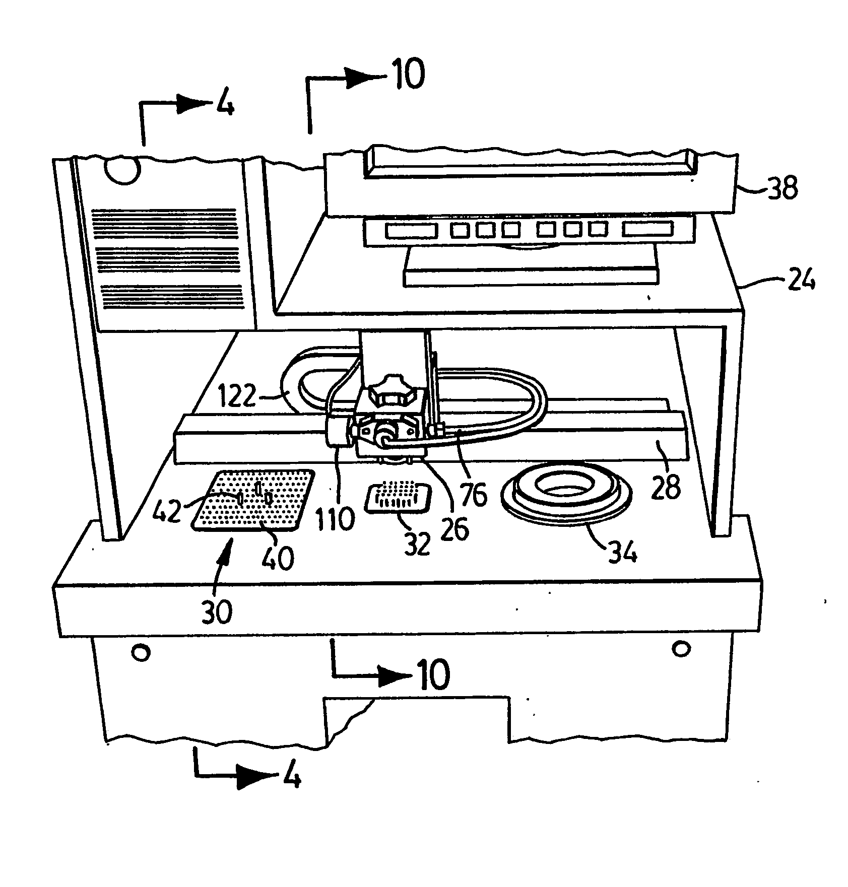
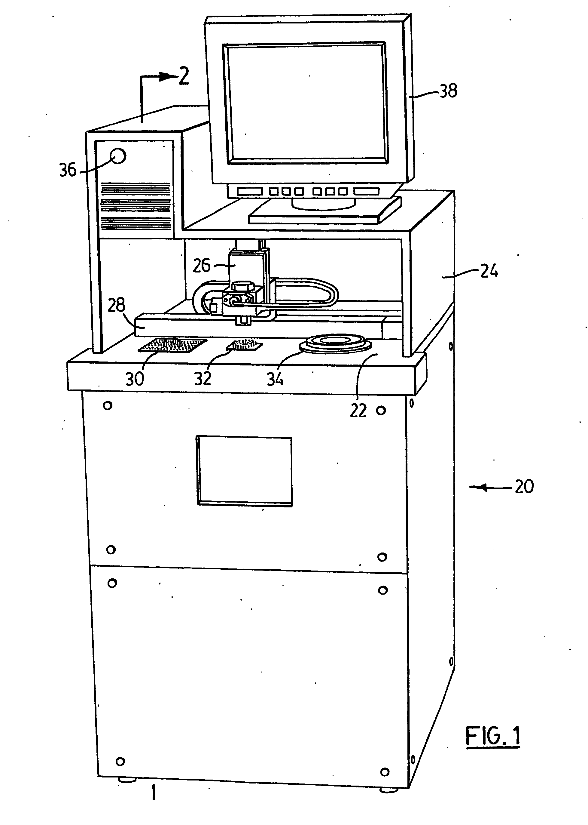
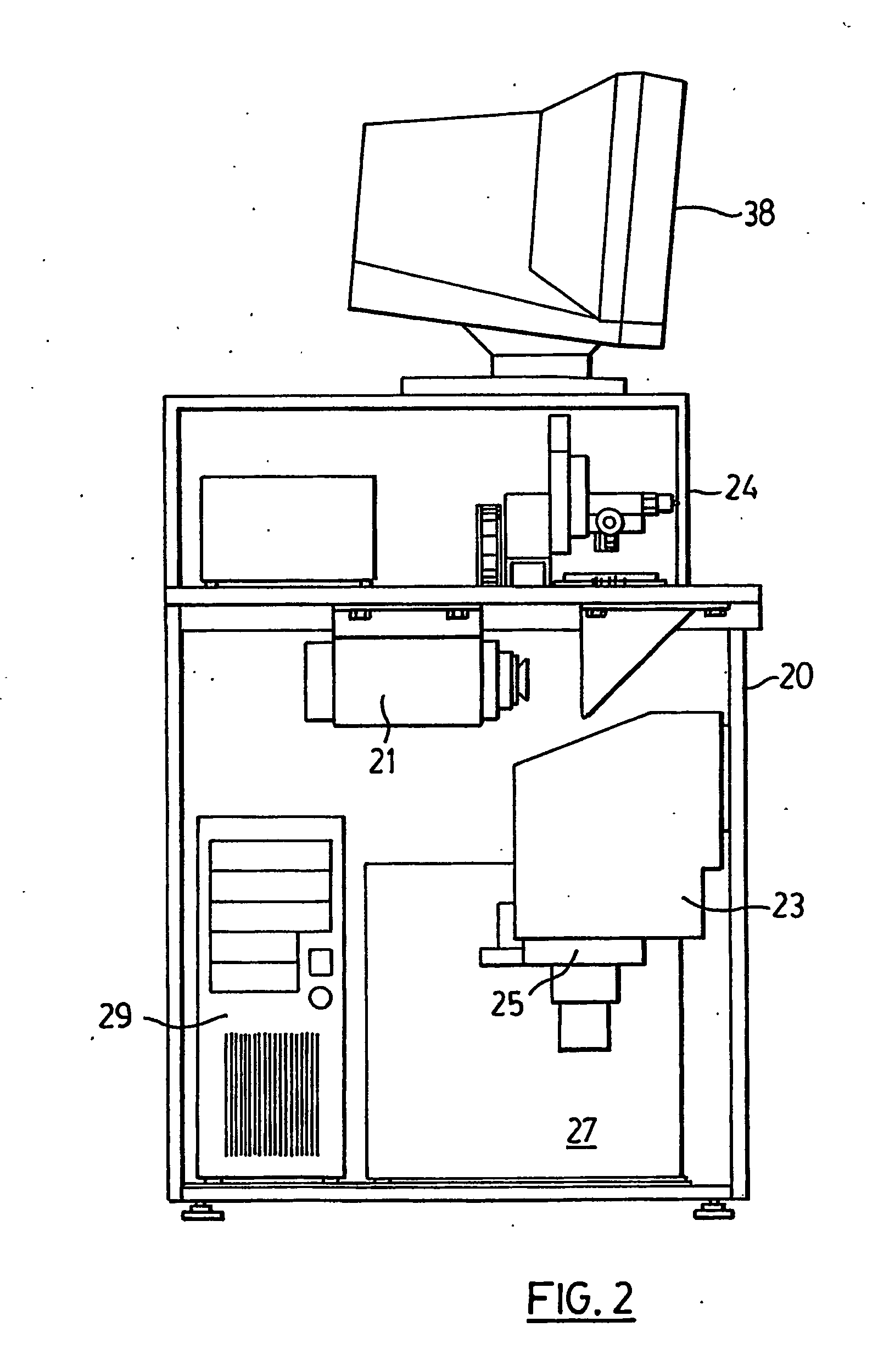
[0087] An apparatus for blocking an ophthalmic lens according to the present invention is generally indicated by reference 20 in the accompanying illustrations. The apparatus 20 includes a cabinet having a top 22 and a hood structure 24 for partially enclosing the top 22. A lens transporter 26 is moveably mounted on a first linear actuator 28 affixed to the top 22. The first linear actuator 28 has a first servo motor or stepper motor unit for moving the lens transporter therealong and for monitoring its position.

[0088] The apparatus 20 has, aligned with the first linear actuator 28 and incorporated into the top 22 of the cabinet, a first station 30, a probing station 32 and a lens blocking station 34. The apparatus 20 encloses a camera 21 focused on the first station 30, an adhesive reservoir 23 and a pumping unit 25 for pumping the adhesive to the blocking station 34. The apparatus further includes a controller in the form of a central processing unit 29 for controlling its operat...


PUM

PropertyMeasurementUnit
temperaturesaaaaaaaaaa
wavelengthaaaaaaaaaa
peak poweraaaaaaaaaa

Abstract

A method is provided for blocking a lens according to which a lens block is obtained which transmits UV and visible light. An adhesive curable by light within the UV and visible spectrum is applied between the lens blank and a lens mounting face of the lens block. The lens blank is placed adjacent the lens block with the adhesive extending therebetween. UV light is applied to cure the adhesive. The adhesive is selected to have a suitable low dimensional change on setting so as not to impart any undue stresses on the lens blank which being capable of total adhesive failure without lens damage or leaving a residue upon application of a suitable stripping force.

Description

FIELD OF THE INVENTION [0001] The present invention relates to the bonding of an ophthalmic lens blank to a lens support block (“lens block”) for supporting the lens blank during a lens generating process. More particularly the present invention relates to the use of an adhesive which is curable by light in the ultraviolet (“UV”) and high visible spectrum as a bonding agent. BACKGROUND OF THE INVENTION [0002] An ophthalmic lens blank generally has a first face with a predetermined curvature and a second face, opposite the first face on which a desired surface contour is generated by a machining process. The overall process is generally referred to as “lens generation” and the overall object is to yield a finished lens wherein the first and second face curvatures cooperate to yield desired optical properties. [0003] Lens surfacing is carried out using profiling machines which typically have a cutter of some type which is moved across the second face. The lens blank may be stationary ...

Claims


Application Information

Patent Timeline
Patent Type & Authority Applications(United States)
IPC IPC(8): G02C7/02B24B13/005B29D11/00C03C17/32C08F265/04C09D175/16C09J4/06C09J151/00C09J151/08C09J175/16
CPCB24B13/005B24B13/0055C09J175/16C09J151/08C09J151/003C09J4/06C09D175/16B29D11/00942C03C17/32C08F265/04C08F283/00C08L2666/02
Inventor SAVOIE, MARCCULF, ADRIAN
Owner MICRO OPTICS DESIGN
Why Eureka
Try Eureka