Plasma on demand tube

a plasma tube and plasma technology, applied in the field of plasma on demand tube, can solve the problems of inadequate vacuum force between the upstream tube and downstream tube, blood cells clogging the filter, and the vacuum force generated by the evacuated device is not adequate to draw plasma from a collected blood sample, so as to achieve convenient use and less prone to clogging with aggregated blood cells

Active Publication Date: 2005-06-30
BECTON DICKINSON & CO
View PDF12 Cites 41 Cited by
  • Summary
  • Abstract
  • Description
  • Claims
  • Application Information

AI Technical Summary

Benefits of technology

[0011] Generally, the present invention is directed to a device for separating plasma from whole blood, including a primary collection chamber having a blood agglutinating agent and an anticoagulant deposited therein, and a porous filter separating the primary collection chamber from a secondary collection chamber. A transfer device having at least one needle may be provided to transfer plasma from the primary collection chamber to the secondary collection chamber. The invention is an improvement over the prior art as it is capable of providing sufficient force by the vacuum in the evacuated tubes to separate plasma from agglutinated, but uncoagulated, blood cells with a large pore filter that is less prone to clogging with aggregated blood cells. The use of an agglutinating agent to aggregate the cells, in combination with a filter having a larger pore size, permits separation of plasma from the aggregated cells with the use of conventional evacuated tubes, which, because of this combination, have adequate vacuum to draw the plasma through the filter. The invention is a further improvement over the prior art as it is easy to use in clinical and research applications. The invention is an even further improvement over the prior art as it is capable of providing an uncontaminated plasma specimen that is separated from a whole blood sample.

Problems solved by technology

In addition, the prior art devices typically use a filter membrane having small and fine pore sizes to prevent cellular components from passing therethrough, which can render the vacuum forces generated by the evacuated device inadequate to drawn plasma from a collected blood sample.
Problems that exist with this disclosure are blood cells clogging the filter and an inadequate vacuum force between the upstream tube and downstream tube during blood collection.
A further problem that exists with this disclosure is exposing any plasma collected in the downstream tube to contaminants should the downstream tube be removed from the upstream tube.
Konrad does not disclose plasma separation from whole blood.

Method used


Image

  • Plasma on demand tube
  • Plasma on demand tube
  • Plasma on demand tube

Examples


second embodiment

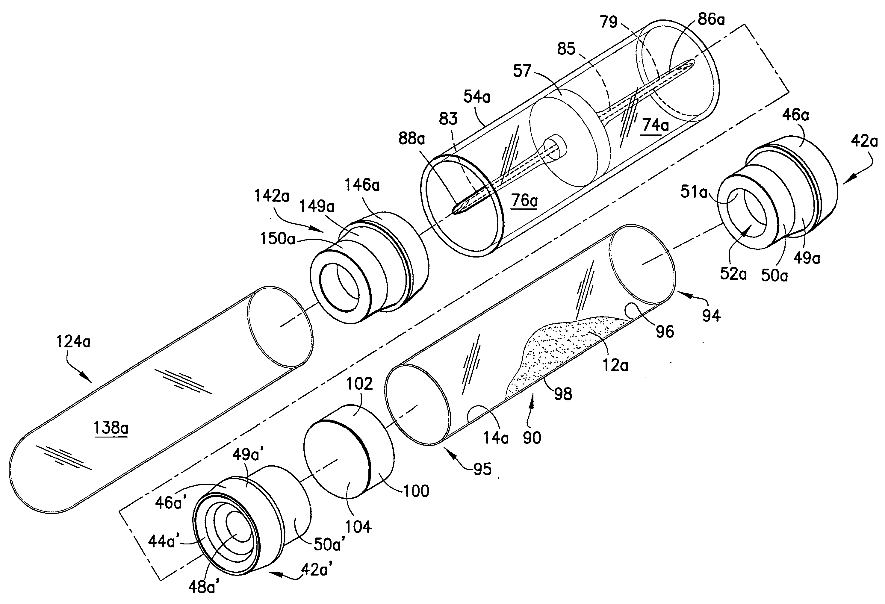
[0050] As shown in detail in FIGS. 4 through 6, in the present invention, collection tube 90 comprises a hollow cylindrical tube including generally cylindrical tubular wall 92 extending between a first open end 94 and a second open end 95. First and second open ends 94 and 95 are hermetically-sealed with rubber stoppers 42a and 42a′, respectively, such as rubber stopper 42 as previously described herein. Tubular wall 92 has interior surface 96 and exterior surface 98. Collection tube 90 is comprised of suitable material which is impermeable to gas and liquid, and is desirably made of glass or molded plastic. Optionally, vent needle 16a is provided for use with rubber stopper 42a of collection tube 90.

first embodiment

[0051] Similar to the previous first embodiment of primary tube 24, rubber stoppers 42a, 42a′ are hermetically sealed at circumferential surface 49a, 49a′ of depending portion 50a, 50a′ to interior surface 96 at the first open upstream end 94 and the second open downstream end 95 of collection tube 90.

[0052] Cylindrical porous filter 100 is positioned within collection tube 90 and affixed along circumferential surface 102 of filter 100 to interior surface 96 of collection tube 90. Porous filter 100 is positioned so that downstream surface 104 of filter 100 abuts up against depending portion 50a′ of downstream rubber stopper 42a′. Abutting porous filter 100 against downstream rubber stopper 42a′ encloses cavity 52a′ of depending portion 50a′ of rubber stopper 42a′. The interior surface 96 of collection tube 90 between interior surface 51a of cavity 52a of depending portion 50a of upstream rubber stopper 42a and upstream surface 106 of porous filter 100 define primary collection chamb...


PUM

PropertyMeasurementUnit
pore sizeaaaaaaaaaa
porosity sizeaaaaaaaaaa
pore sizeaaaaaaaaaa

Abstract

A device for separating plasma from whole blood is provided having an evacuated primary collection chamber capable of fluid communication through a porous filter to an evacuated secondary collection chamber. An agglutinating agent is provided within the primary collection chamber so as to aggregate blood cells within a whole blood sample. The porous filter has a pore size which is small enough to capture the aggregated blood cells therein, yet large enough to permit plasma to transfer therethrough under pressures associated with conventional evacuated blood collection tubes. The primary and secondary collection chambers may be provided in separate containers or tubes, with transfer occurring therebetween through a transfer device including the porous filter therein.

Description

CROSS-REFERENCE TO RELATED APPLICATION [0001] This application claims the benefit of U.S. Provisional Application No. 60 / 532,509, filed Dec. 24, 2003.BACKGROUND OF THE INVENTION [0002] 1. Field of the Invention [0003] The present invention relates to separation of plasma from whole blood. Particularly, the present invention relates to a medical device capable of separating plasma from agglutinated blood cells through a porous filter membrane. [0004] 2. Description of Related Art [0005] Plasma is the liquid portion of blood primarily comprised of water. The water portion of the plasma is freely transferable with cells of the body and other extra cellular fluids. Plasma is also comprised of salts, glucose, amino acids, vitamins, hormones and metabolic waste products. As a whole, plasma provides the means to suspend white blood cells, red blood cells and other cellular components for transfer through a human or animal. If a plasma sample is desired, separation from the other cellular c...

Claims


Application Information

Patent Timeline
Patent Type & Authority Applications(United States)
IPC IPC(8): B01L3/00B01L3/14G01N33/49
CPCB01L3/5082B01L3/5635G01N33/491B01L2400/049B01L2300/0681
Inventor MANOUSSAKIS, DIMITRIOSLOSADA, ROBERT J.
Owner BECTON DICKINSON & CO
Why Eureka
Try Eureka