Face image detecting method, face image detecting system and face image detecting program

Inactive Publication Date: 2005-06-30
SEIKO EPSON CORP
7 Cites 27 Cited by

AI-Extracted Technical Summary

Problems solved by technology

However, in the pattern recognition of a human image, an object, landscape and so on, e.g., an image scanned from a digital camera and so on, it is known that it is still difficult to accurately and quickly identify whether a human face is visible in the image or not.
In the conventional technology, however, although a human face is detected from an image based on “flesh color”, there is a problem that...

Benefits of technology

[0046] Thereby, as in Aspect 5, whether a human face image exists or not in the selected detection target area can be quickly and accurately detected, and, as in Aspect 12, si...

Abstract

A face image detecting method, detecting system and detecting program are provided. After dividing the detection target area into a plurality of blocks and dimensionally compressing the area, feature vectors including a representative value in each block are calculated and then a discriminator detects whether the face image exists or not in the detection target area by using the feature vectors. The discriminator detects after an image feature quantity is dimensionally compressed to the extent of not damaging the feature of face image. Since the number of image feature items to be used for discrimination is substantially reduced from the number of pixels within the detection target area to that of blocks, the number of operations drastically decreases and a face image can be quickly detected.

Application Domain

Image analysisPhotometry +7

Technology Topic

Imaging FeatureRapid detection +3

Image

  • Face image detecting method, face image detecting system and face image detecting program
  • Face image detecting method, face image detecting system and face image detecting program
  • Face image detecting method, face image detecting system and face image detecting program

Examples

  • Experimental program(1)

Example

[0056] A best mode for carrying out the invention will be described with reference to drawings.
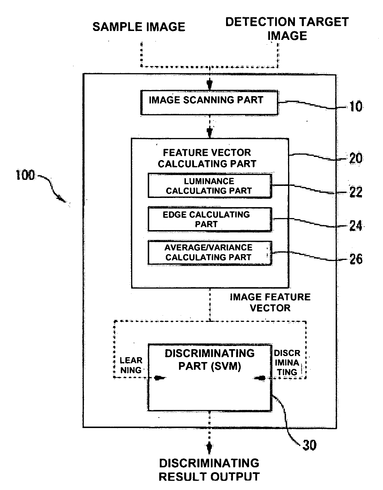
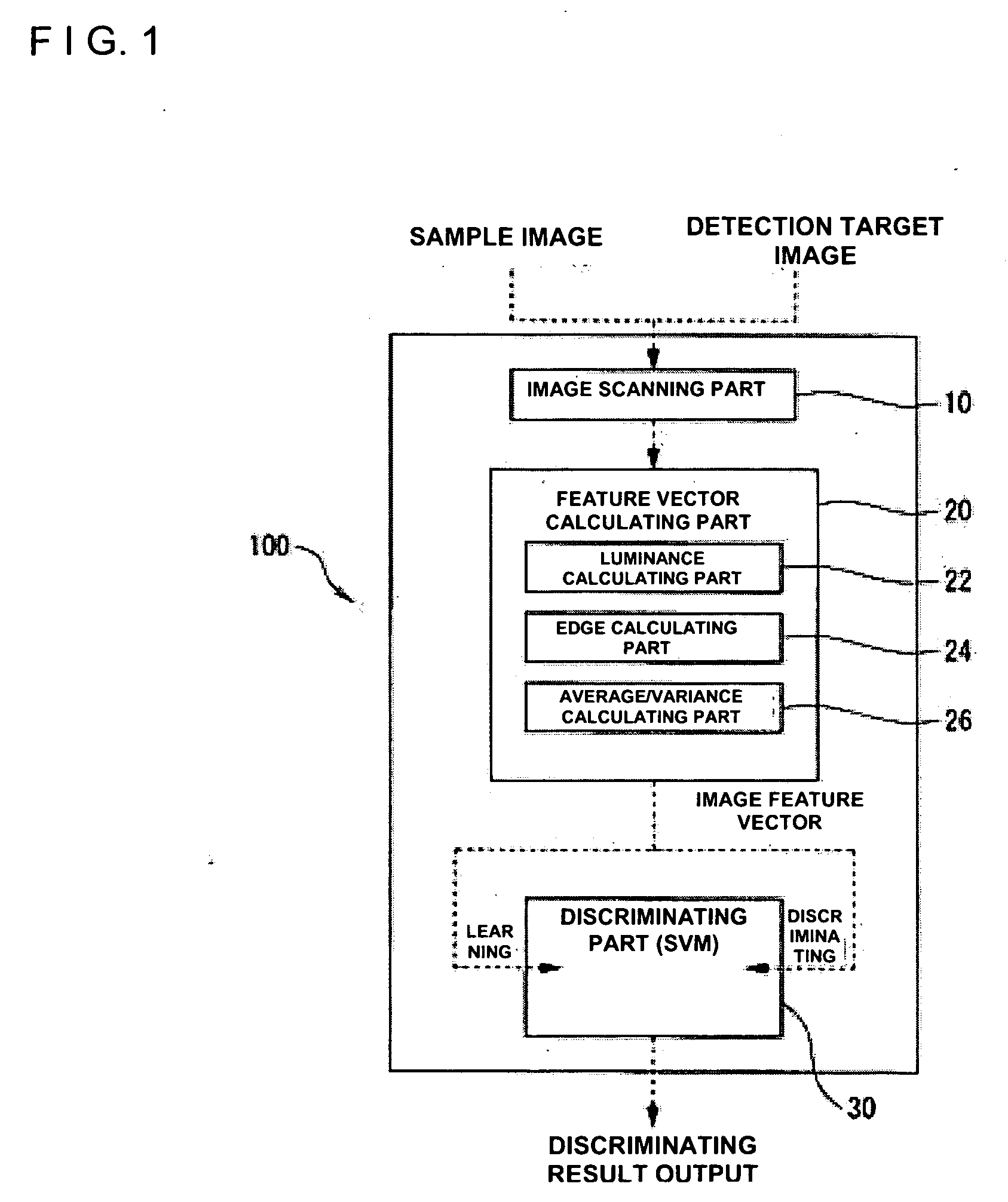
[0057]FIG. 1 shows one embodiment of a face image detecting system 100 according to the invention.
[0058] As shown in this Figure, the face image detecting system 100 comprises: an image scanning part 10 for scanning a sample face image for learning and a detection target image; a feature vector calculating part 20 for generating a feature vector of the image scanned in the image scanning part 10; a discriminating part 30, an SVM (support vector machine), for discriminating whether the detection target image is a face image candidate area or not from the feature vector generated in the feature vector calculating part 20.
[0059] More specifically, the image scanning part 10 includes the CCD (Charge Coupled Device) of digital still camera and of digital video camera, a camera, a vidicon camera, an image scanner, a drum scanner and so on. There is provided a function of A/D converting a specific area within the scanned detection target image and a plurality of face images and non-face images to be sample images for learning and a function of sending the digital data sequentially to the feature vector calculating part 20.
[0060] The feature vector calculating part 20 further comprises: a luminance calculating part 22 for calculating a luminance (Y) in the image; an edge calculating part 24 for calculating edge strength in the image; and an average/variance calculating part 26 for calculating edge strength generated in the edge calculating part 24, an average of a luminance generated in the luminance calculating part 22 or a variance of edge strength. An image feature vector in each sample image and detection target image is generated from a pixel value sampled in the average/variance calculating part 26 and the image feature vector is sent sequentially to the SVM 30.
[0061] The SVM 30 provides a function of learning the image feature vector of a plurality of face images and non-face images to be samples for learning generated in the feature vector calculating part 20 and a function of discriminating from the learning results whether a specific area within the detection target image generated in the feature vector calculating part 20 is a face image candidate area or not.
[0062] The SVM 30, as described above, is a learning machine capable of obtaining a hyperplane most suitable for separating all input data linearly by using an index called margin, and it is known that high discrimination ability can be exerted by using a technique called “kernel trick” even in the case where it is impossible to separate linearly.
[0063] The SVM 30 used in this embodiment has: 1. a learning step and 2. a discriminating step.
[0064] First in 1, the learning step, as shown in FIG. 1, after scanning many face images and non-face images to be sample images for learning in the image scanning part 10, a feature vector in each image is generated in the feature vector calculating part 20 and learned as an image feature vector.
[0065] Next in 2, the discriminating step, by sequentially scanning a specific selection area within the detection target image, generating the image feature vector in the feature vector calculating part 20 and inputting the image feature vector as a feature vector, it is detected whether or not the area has high possibility for the face image to exist according to the area in the hyperplane to be discriminated under which the input image feature vector falls.
[0066] Here, with regard to the sizes of sample face image and non-face image for learning, as will be described later, the image with 24-pixels by 24-pixels is blocked into a specific number, for example. Blocking is performed on the area having the same size as the size of the area to be detected after blocking.
[0067] Explaining rather in detail about this SVM based on the description in pp. 107-118 of pattern ninshiki to gakusyuu no toukeigaku (Iwanami Shoten, Publishers, co-authored by: Asou Hideki; Tsuda Kouji; and Murata Noboru), when the problem to be discriminated is nonlinear, a nonlinear kernel function can be used in the SVM. The identification function in this case will be expressed by the following Formula 1.
[0068] In other words, Formula 1 with “zero” value leads to the hyperplane to be discriminated. The value other than “zero” leads to a distance from the hyperplane to be discriminated calculated from a given image feature vector. The result of formula 1 with nonnegative leads to a face image while with negative leads to a non-face image. f ⁡ ( ϕ ⁡ ( x ) ) = ∑ i = 1 n ⁢ ⁢ α i * y i * K ⁡ ( x , x i ) + b Formula ⁢ ⁢ 1
[0069] In this formula, x denotes a feature vector and xi denotes a support vector. As x and xi, the values generated in the feature vector calculating part 20 are used. K denotes a kernel function and in this embodiment the function of following formula 2 will be used.
K(x, xi)=(a*x*xi+b)T Formula 2
[0070] (wherein a=1, b=0, T=2)
[0071] In addition, each of the feature vector calculating part 20, the SVM 30, the image scanning part 10 and so on configuring the face image detecting system 100 is actually realized by a computer system such as a PC which is configured by hardware configured by a CPU, RAM and so on and which is configured by a special computer program (software).
[0072] In the hardware for realizing the face image detecting system 100 as shown in FIG. 2, for example, through various internal/external buses 47 such as a processor bus, a memory bus, a system bus and an I/O bus which are configured by a PCI (Peripheral Component Interconnect) bus, ISA (Industrial Standard Architecture) bus and so on, there are bus-connected to each other: CPU (Central Processing Unit) 40 for performing various controls and arithmetic processing; RAM (Random Access Memory) 41 used for a main storage; ROM (Read Only Memory) 42 which is a read-only storage device; a secondary storage 43 such as a hard disk drive (HDD) and a semiconductor memory; an output unit 44 configured by a monitor (LCD (liquid crystal display) and a CRT (cathode-ray tube)) and so on; an input unit 45 configured by an image picking sensor and so on such as an image scanner, a keyboard, a mouse, CCD (Charge Coupled Device) and CMOS (Complementary Metal Oxide Semiconductor); an I/O interface (I/F) 46; and so on.
[0073] Then, for example, various control programs and data that are supplied through a storage medium such as CD-ROM, DVD-ROM and a flexible disk (FD) and through a communication network (LAN, WAN, Internet and so on) N are installed on the secondary storage 43 and so on. At the same time, the programs and data are loaded onto the main storage 41 if necessary. According to the programs loaded onto the main storage 41, the CPU 44 performs a specific control and arithmetic processing by using various resources. The processing result (processing data) is output to the output unit 44 through the bus 47 and displayed. The data is properly stored and saved (updated) in the database created by the secondary storage 43 if necessary.
[0074] A description will be given about an example of a face image detecting method using the face image detecting system 100.
[0075]FIG. 3 is a flowchart showing an example of a face image detecting method for an image to be detected actually. Before discriminating by using an actual detection target image, it is necessary to go through a step of learning a face image and a non-face image to be sample images for learning for the SVM 30 to be used for discrimination as described above.
[0076] In the learning step, after generating feature vectors in each face image and non-face image to be sample images the feature vectors are input with the information indicating whether the image is a face image or a non-face image. In addition, it is preferable that the image in which the same process is done as in the selected area in the actual detection target image is used for the image for learning used here for learning. In other words, as will be described later, since the image area in the invention to be a discrimination target is dimensionally compressed, discrimination can be performed more quickly and accurately by using the image which has been compressed to the same dimension as in the image area.
[0077] When the learning of feature vector of the sample image for the SVM 30 has been finished, first the area to be a detection target within the detection target image will be determined (selected) as shown in step S101 in FIG. 3. In addition, the method for determining the detection target area is not limited in particular, and the area obtained in another face image discrimination method may be adopted as it is, or the area arbitrarily specified within the detection target image by a user of the system and so on. However, since in most cases it is not known whether the face image is included or not as well as where the face image included in principle, it is preferable that whole area is very carefully searched to select an area by beginning from a specific area setting the origin at the upper left corner of the target image area and by shifting by a specific pixel in horizontal and vertical directions, for example. Also, the size of the area is not necessarily uniform, and selection may be made by changing the size properly.
[0078] Then when the first area to be the detection target of face image has been selected, moving to step S103 and the size of the first detection target area is resized at a specific size, for example, 24-pixels by 24-pixels. In other words, since the size of the detection target area is unclear as well as it is unclear that whether the face image is included in the image or not, the number of pixels becomes significantly different depending on the size of face image in the area to be selected. Therefore, the size of the selected area is resized at a standard size (24-pixels by 24-pixels) for the moment.
[0079] Next, when resizing of the selected area has been finished, moving to step S105 and calculating edge strength of the resized area in each pixel, the area is divided into a plurality of blocks to calculate the average or variance of edge strength within each block.
[0080]FIG. 4 is an image showing the change of edge strength after resized, in which the calculated edge strength is indicated as 24-pixels by 24-pixels. Also in FIG. 5, the area is further blocked by 6-pixels by 8-pixels and the average of edge strength in each block is indicated as the representative value of each block. Further in FIG. 6, the area is further blocked by 6-pixels by 8-pixels and the variance of edge strength in each block is indicated as the representative value of each block. In these Figures, in addition, the edge parts at both ends of the upper block show “both eyes” of human face, the edge part at the center of the central block shows the “nose” and the edge part at the center of the lower block shows the “lips” of a human face. As in the invention, it is clear the feature of a face image is left as it is even when the dimension is compressed.
[0081] With regard to the number of blocks in the area, it is critically important to block based on an auto-correlation coefficient to the extent of not damaging the image feature quantity. When the number of blocks becomes too large, the number of image feature vectors to be calculated increases accordingly and the processing load will increase. Therefore, the acceleration of detection cannot be achieved. In other words, when an auto-correlation coefficient is a threshold value or more, it is conceivable that the value of the image feature quantity or the changing pattern within the block falls within a specific range.
[0082] The auto-correlation coefficient can be calculated by the following Formulae 3 and 4. Formula 3 yields the auto-correlation coefficient in a horizontal (width) direction (H) of the detection target image while by Formula 4 yields the auto-correlation coefficient in a vertical (height) direction (V) of the detection target image. h ⁡ ( j , ⅆ x ) = ⁢ ∑ i = 0 i = width - 1 ⁢ ⅇ ⁡ ( ⅈ + ⅆ x , j ) · ⅇ ⁡ ( ⅈ , j ) ∑ i = 0 i = width - 1 ⁢ ⅇ ⁡ ( ⅈ , j ) · ⅇ ⁡ ( ⅈ , j ) Formula ⁢ ⁢ 3 [0083] r: correlation coefficient [0084] e: luminance or edge strength [0085] width: number of pixels in a horizontal direction [0086] i: pixel location in a horizontal direction [0087] j: pixel location in a vertical direction [0088] dx: distance between pixels v ⁡ ( ⅈ , ⅆ y ) = ∑ j = 0 j = height - 1 ⁢ ⁢ ⅇ ⁡ ( ⅈ , j ) · ⅇ ⁡ ( ⅈ , j + ⅆ y ) ∑ j = 0 j = height - 1 ⁢ ⅇ ⁡ ( ⅈ , j ) · ⅇ ⁡ ( ⅈ , j ) Formula ⁢ ⁢ 4 [0089] v: correlation coefficient [0090] e: luminance or edge strength [0091] height: number of pixels in a vertical direction [0092] i: pixel location in a horizontal direction [0093] j: pixel location in a vertical direction [0094] dy: distance between pixels
[0095]FIGS. 7 and 8 show examples of correlation coefficients in the horizontal (H) and vertical (V) directions obtained by using Formulae 3 and 4, respectively.
[0096] As shown in FIG. 7, when one image shifts in a horizontal direction by “zero” relative to the standard image, in other words, when both images completely overlap each other, a correlation between both images is “1.0” (maximum). When one image shifts in a horizontal direction by “one” pixel relative to the standard image, a correlation between both images changes to about “0.9”, also, when one image shifts in a horizontal direction by “two” pixels, a correlation between both images changes to about “0.75”, which shows that the increase in the shift (number of pixels) in a horizontal direction gradually decreases the correlation between both images.
[0097] Also, as shown in FIG. 8, when one image shifts in a vertical direction by “zero” relative to the standard image, in other words, when both images completely overlap each other, a correlation between both images is “1.0” (maximum). When one image shifts in a vertical direction by “one” pixel relative to the standard image, a correlation between both images changes to about “0.8”, also, when one image shifts in a vertical direction by “two” pixels, a correlation between both images changes to about “0.65”, which shows that the increase in the shift (number of pixels) in a vertical direction also gradually decreases the correlation between both images.
[0098] As a result, when the shift is relatively small, in other words, within a range of a certain number of pixels, the difference between both images in image feature quantities is small and it is conceivable that the image feature quantities in the images are almost the same.
[0099] In this embodiment, the range in which the value of the image feature quantity or the changing pattern is considered to be constant (threshold value or less) is up to “four” pixels in a horizontal direction and “3” pixels in a vertical direction as shown by an arrow in FIGS. 7 and 8 although the range changes according to detection speed, detection reliability and so on. With the shift within this range, since the change of the image feature quantity is small, the range may be treated as the range of shift within a certain range. In this embodiment as a result, the image area can be compressed dimensionally up to {fraction (1/12)} (6×8=48 dimensions/24×24=576 dimensions) without damaging the feature of the originally-selected area.
[0100] As described above, the invention has been worked out by focusing on the fact that the image feature quantity has a certain range, in which the range in which the auto-correlation coefficient does not fall below a certain value is treated as one block, and the image feature vector constituted by the representative value in each block is employed.
[0101] When the detection target area has been dimensionally compressed in this way, calculating the image feature vector constituted by the representative value in each block and it is detected whether the face image exists or not in the area by inputting the obtained feature vector into the discriminator (SVM) 30 (step S109).
[0102] Then the detection result is shown to a user every time the detection ends or together with other detection results collectively, and moving to step S110, the process ends after the detection process is performed on all areas.
[0103] In the examples of FIGS. 4-6, each block consists of 12 (3 by 4) pixels the auto-correlation coefficients of which do not fall below a constant value and which abut each other vertically and horizontally. The average (FIG. 5) and variance (FIG. 6) of the image feature quantity (edge strength) of these 12 pixels are calculated as the representative values of each block. The image feature vectors obtained from the representative values are input into the discriminator (SVM) 30 to perform the detection process.
[0104] In the invention, since the discrimination is performed after dimensionally compressing to the extent of not damaging the original feature quantities of the face image, without using all the image feature quantities in the detection target area as they are, the number of calculations can be greatly reduced, so that whether the face image exists or not in the selected area can be quickly and accurately detected.
[0105] In this embodiment, in addition, although an image feature quantity based on edge strength is adopted, an image feature quantity based singly on luminance or both luminance and edge strength may be used in the case where the image can be dimensionally compressed more effectively by using the luminance of pixels than by using edge strength depending on the type of image.
[0106] Also in the invention, although a “human face” which is the most likely candidate is targeted for the detection target image, other objects such as a “human body type”, “animal face and posture”, “vehicle such as a car”, “building”, “plant” and “topographical formation” can be targeted as well as a “human face”.
[0107] In addition, FIG. 9 shows a “Sobel operator” which is a difference type edge detection operator applicable to the invention.
[0108] An operator (filter) shown in FIG. 9(a) accentuates an edge in a horizontal direction by adjusting each group of three pixel values located in left and right rows among eight pixel values surrounding a target pixel. An operator shown in FIG. 9(b) accentuates edges in a vertical direction by adjusting each group of three pixel values located in an upper line and lower row among eight pixel values surrounding a target pixel. Thereby the edges in the vertical and horizontal directions can be detected.
[0109] By obtaining edge strength by calculating a square root after calculating a square sum of the results generated in each operator, and by generating edge strength or edge variance in each pixel, the image feature vector can be accurately detected. In addition, as described above, other difference type edge detection operators such as “Roberts” and “Prewitt” and a template type edge detection operator can be applied in place of the “Sobel operator”.
[0110] Discrimination with high speed and high accuracy can be made by using a neural network in place of the SVM as the discriminator 30.

PUM

no PUM

Description & Claims & Application Information

We can also present the details of the Description, Claims and Application information to help users get a comprehensive understanding of the technical details of the patent, such as background art, summary of invention, brief description of drawings, description of embodiments, and other original content. On the other hand, users can also determine the specific scope of protection of the technology through the list of claims; as well as understand the changes in the life cycle of the technology with the presentation of the patent timeline. Login to view more.

Similar technology patents

OFDM Receiving Apparatus and Mode Detecting Method Thereof

InactiveUS20090262857A1accurately and quickly detectchip size be reduce
Owner:CORELOGIC

Method and Apparatus for Fast Fault Detection

ActiveUS20100026276A1react quicklyaccurately and quickly detect
Owner:NORTHROP GRUMMAN SYST CORP

Classification and recommendation of technical efficacy words

  • accurately and quickly detect

Method and Apparatus for Fast Fault Detection

ActiveUS20100026276A1react quicklyaccurately and quickly detect
Owner:NORTHROP GRUMMAN SYST CORP

OFDM Receiving Apparatus and Mode Detecting Method Thereof

InactiveUS20090262857A1accurately and quickly detectchip size be reduce
Owner:CORELOGIC
Why Eureka
Try Eureka