Control apparatus for electrical generator of motor vehicle

Active Publication Date: 2005-06-30
DENSO CORP
View PDF20 Cites 2 Cited by
  • Summary
  • Abstract
  • Description
  • Claims
  • Application Information

AI Technical Summary

Benefits of technology

[0020] In that way, it becomes possible to use a standard type of ECU for generator and engine control, in various different vehicle models, since the type information that is specific to each type of generator is stored in a device that is separate from the ECU. Thus, the number of different types of ECU that must be manufactured can be substantially reduced.
[0021] Alternatively, the memory means of the generator rotation speed derivation apparatus may have control parameter relationship information stored therein which is specific to that type of generator, with that information being transmitted to the main control apparatus via the digital communication link. With such a configuration, the memory means of the main control apparatus has data stored therein which repres

Problems solved by technology

Thus, such a method has the disadvantage that the number of d

Method used


Image

  • Control apparatus for electrical generator of motor vehicle
  • Control apparatus for electrical generator of motor vehicle
  • Control apparatus for electrical generator of motor vehicle

Examples


Example

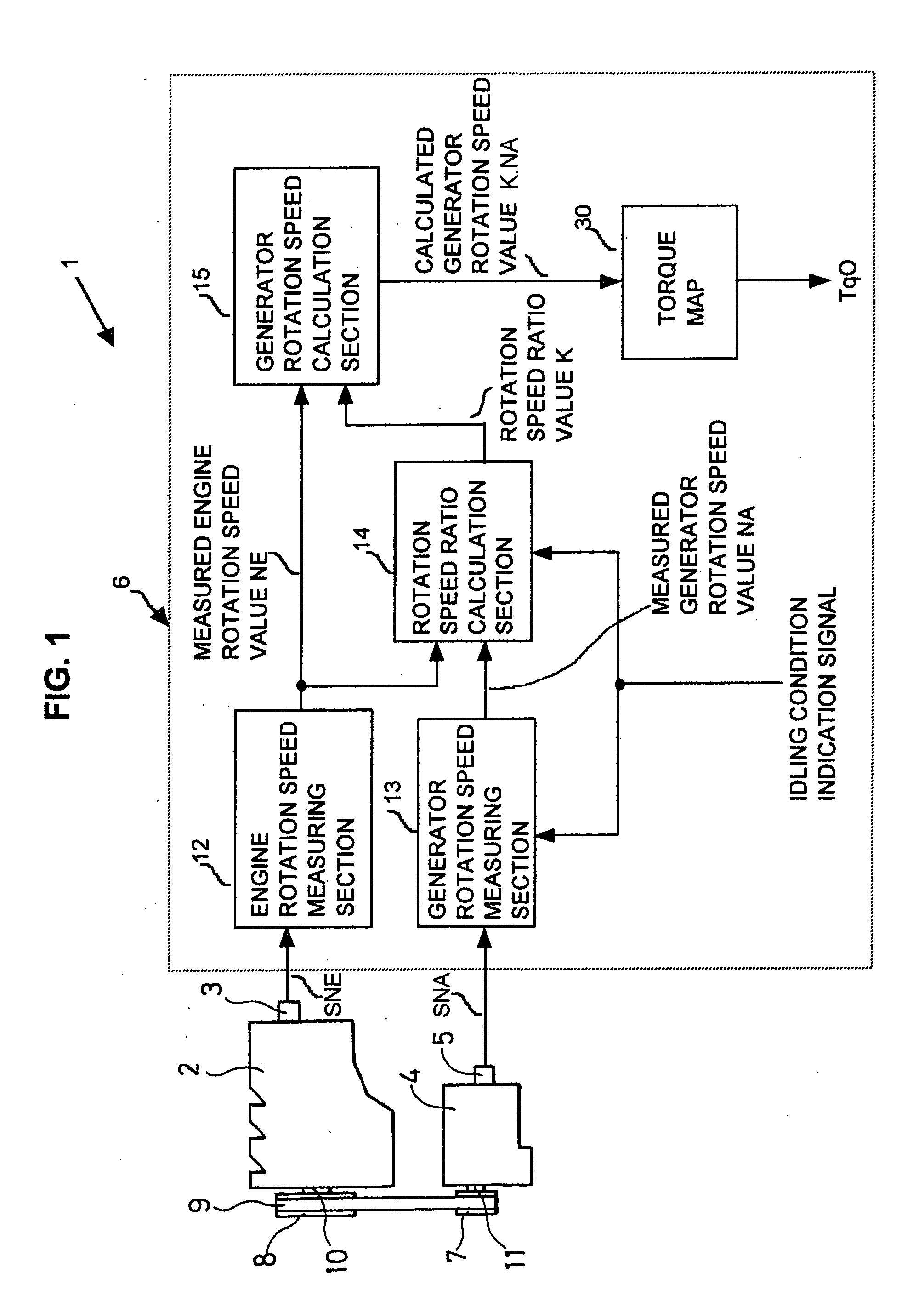
[0027]FIG. 1 is a general system diagram of a first embodiment of a control apparatus for a generator of a motor vehicle, with the control apparatus designated by reference numeral 1. The control apparatus 1 is made up of an ECU 6, a engine rotation sensor 3 and a generator rotation sensor 5. The engine rotation sensor 3 produces a sensor signal referred to in the following as the rotation speed measurement signal SNE, for use in measuring the engine speed of rotation for an engine 2, while the generator rotation sensor 5 produces a detection signal (i.e., the rotation speed measurement signal SNA), for use in measuring the speed of rotation of a rotor of a generator 4, which is driven from the crankshaft 10 of the engine 2 by a timing belt 9 acting on a pulley 8 of the crankshaft 10 and a pulley 7 of the shaft 11 of the generator 4.

[0028] The engine rotation sensor 3 can for example consist of a usual type of electromagnetic sensor, disposed close to teeth that are formed on a mem...

Example

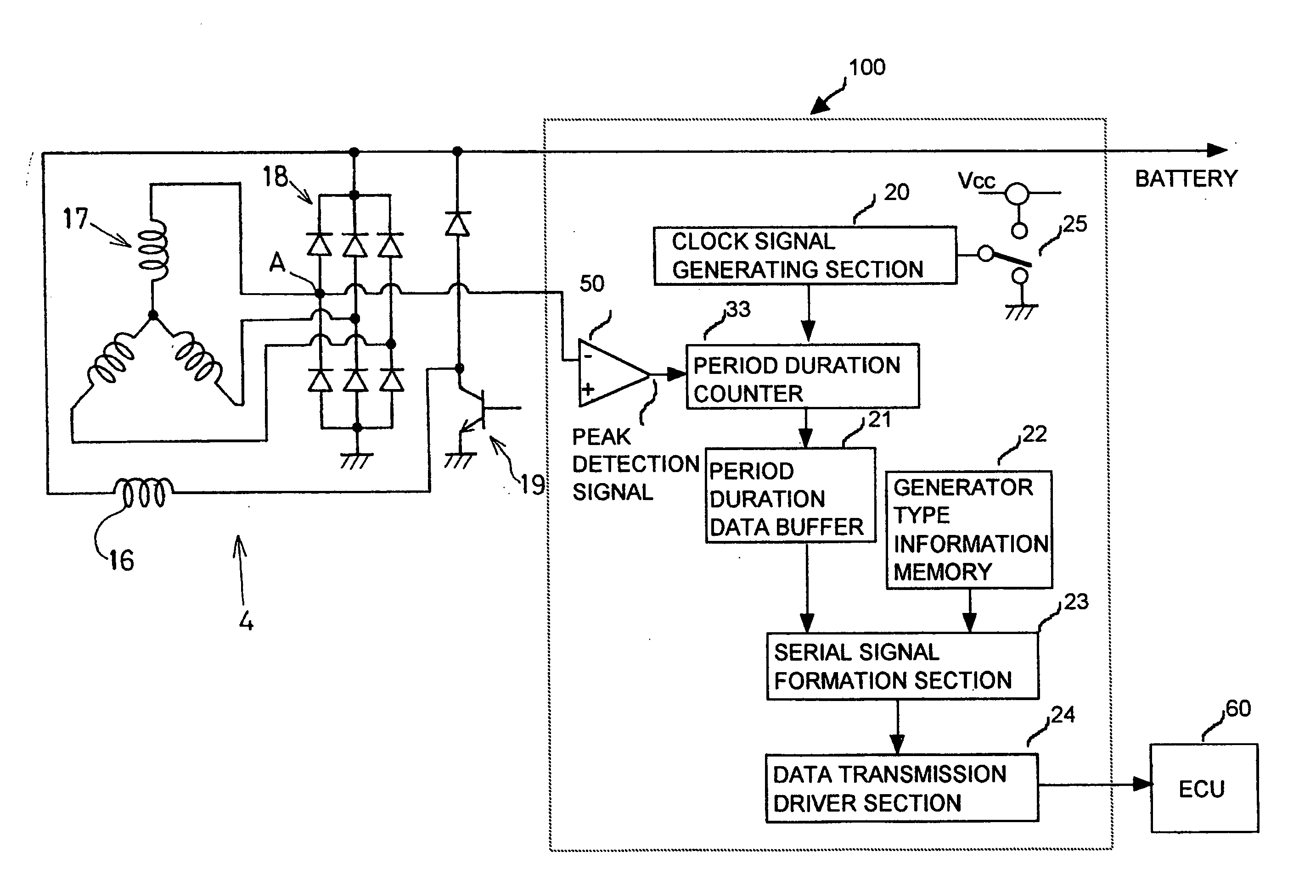
[0038] A second embodiment of a control apparatus for a vehicle generator will be described referring to the general system diagram of FIG. 3. This embodiment basically differs from that of the first embodiment of FIG. 1 in that the function of the generator rotation speed measuring section 13 of the first embodiment (measuring the speed of rotation of the generator 4) is performed by a processing section 100 (referred to in the following as the generator speed measurement apparatus 100) that is implemented by a separate device from the ECU which controls the vehicle engine and the generator 4. That ECU of the second embodiment, designated by numeral 60, also performs the above-described functions of the engine rotation speed measuring section 12, rotation speed ratio calculation section 14 and generator rotation speed calculation section 15 of the first embodiment, and further description of these will be omitted.

[0039] The second embodiment also basically differs from the first e...

Example

Third Embodiment

[0052] A third embodiment of the invention differs from the second embodiment in that the ECU 60 has stored therein a normalized characteristic (such as a torque map) corresponding to a single type of vehicle generator. In that case, the data held stored in the generator type information memory 22 includes relative ratio information that is specific to the type of the generator 4, i.e., information that can be used by the ECU 60 to convert a normalized control parameter characteristic into a characteristic that is suitable for use in controlling the generator 4. The relative ratio information is transferred to the ECU 60 from the generator speed measurement apparatus 100 together with the generator type information, in the same manner as described for the generator type information with the second embodiment. When the relative ratio information is received by the ECU 60, it reads out the stored normalized control parameter characteristic data, and modifies these in ...


PUM


Abstract

A control apparatus such as an ECU, that controls the generator of a vehicle, measures the engine rotation speed and generator rotation speed while the engine is idling, and calculates and stores the ratio of the speed values. Thereafter when the vehicle is being driven and the current value of generator rotation speed is required, it is calculated based on the stored ratio value and the currently measured speed of the engine. The processing load on the ECU is thereby reduced, since generator rotation speed measurement processing is performed only in the idling condition.

Description

CROSS-REFERENCE TO RELATED APPLICATIONS [0001] This application is based on and incorporates herein by reference Japanese Patent Application No. 2003-430917 filed on Dec. 25, 2003. BACKGROUND OF THE INVENTION [0002] 1. Field of Application [0003] The present invention relates to a control apparatus that controls an electrical generator (referred to in the following simply as a generator) of a motor vehicle, and in particular to a control apparatus which derives and utilizes the speed of rotation of the rotor of an alternator that constitutes the generator. [0004] 2. Prior Art Technology [0005] A generator of a motor vehicle is generally an alternator (typically, a 3-phase alternator) having a rotor that is driven by a belt and pulleys, or gears, from the vehicle engine. In the prior art, a type of control apparatus for a generator of a vehicle is known, that is implemented as an electronic control unit (hereinafter referred to as an ECU), with the ECU performing control in accordanc...

Claims


Application Information

Patent Timeline
IPC IPC(8): F02D29/06F01P7/10F02N11/08H02P9/00H02P9/02H02P9/04
CPCF02D29/06
Inventor ASADA, TADATOSHIMAEHARA, FUYUKI
Owner DENSO CORP
Why Eureka
Try Eureka