Motor vehicle passenger compartment heat insulation and dissipation

a technology for passenger compartments and motor vehicles, applied in the field of motor vehicle industry, can solve the problems that the ideal heat exchange system does not give heat an opportunity, and achieve the effect of reducing pollution emissions and reducing energy consumption

Inactive Publication Date: 2005-06-30
MOLLERTECH GMBH
View PDF33 Cites 31 Cited by
  • Summary
  • Abstract
  • Description
  • Claims
  • Application Information

AI Technical Summary

Benefits of technology

[0016] The present invention achieves reduced energy consumption by, and therefore reduced emissions of pollutants from, motor vehicles, preferably in conjunction with the total insulation that is the subject of the above-cited parent patent.
[0017] This is achieved in a manner to substantially reduce the energy required by conventional heating and air conditioning systems to maintain the passenger compartment at a comfortable temperature.

Problems solved by technology

Thus, the ventilating system ideally does not give heat an opportunity to penetrate the insulating part 18 and enter the passenger compartment.

Method used


Image

  • Motor vehicle passenger compartment heat insulation and dissipation
  • Motor vehicle passenger compartment heat insulation and dissipation
  • Motor vehicle passenger compartment heat insulation and dissipation

Examples


Embodiment Construction

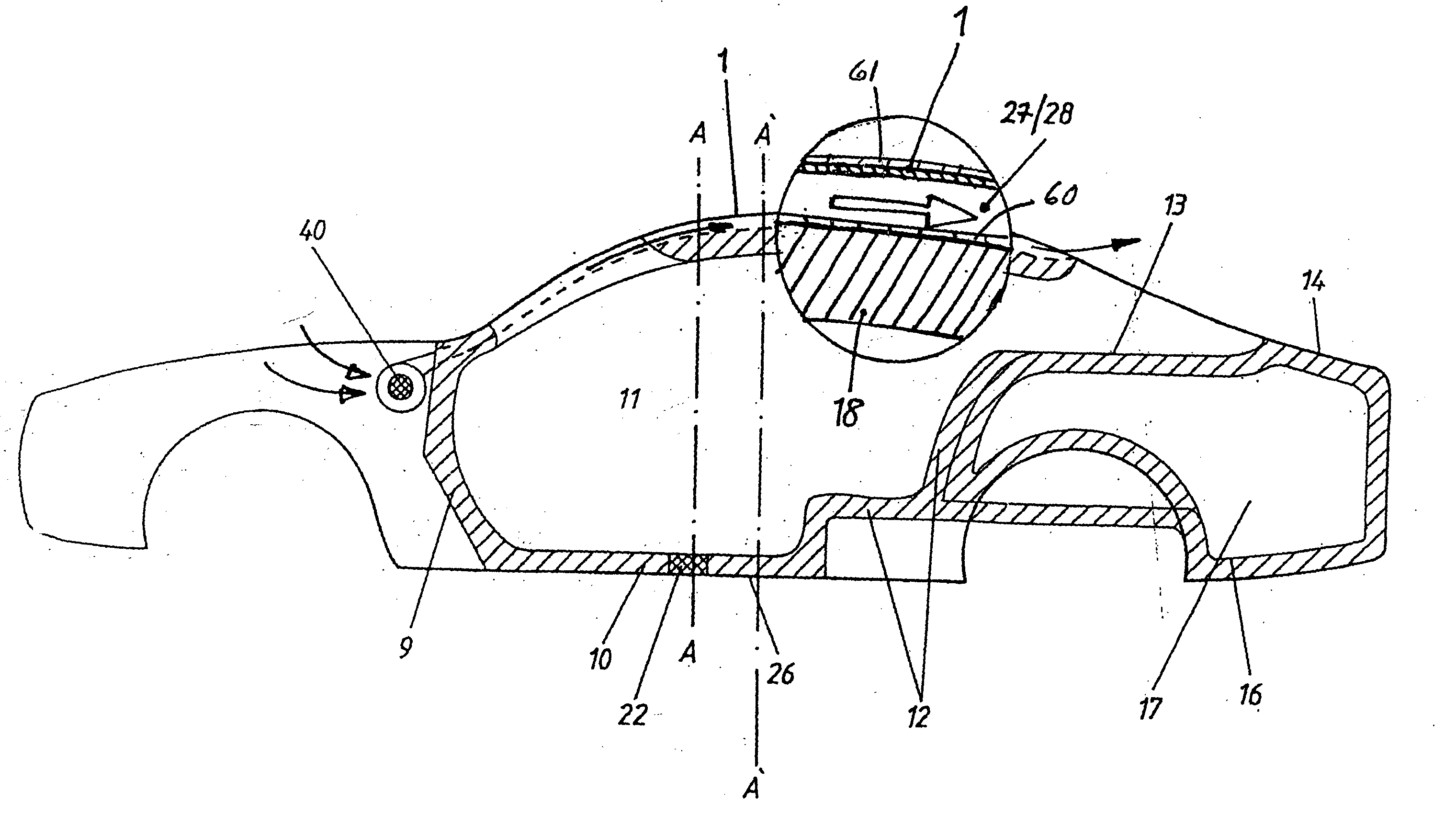
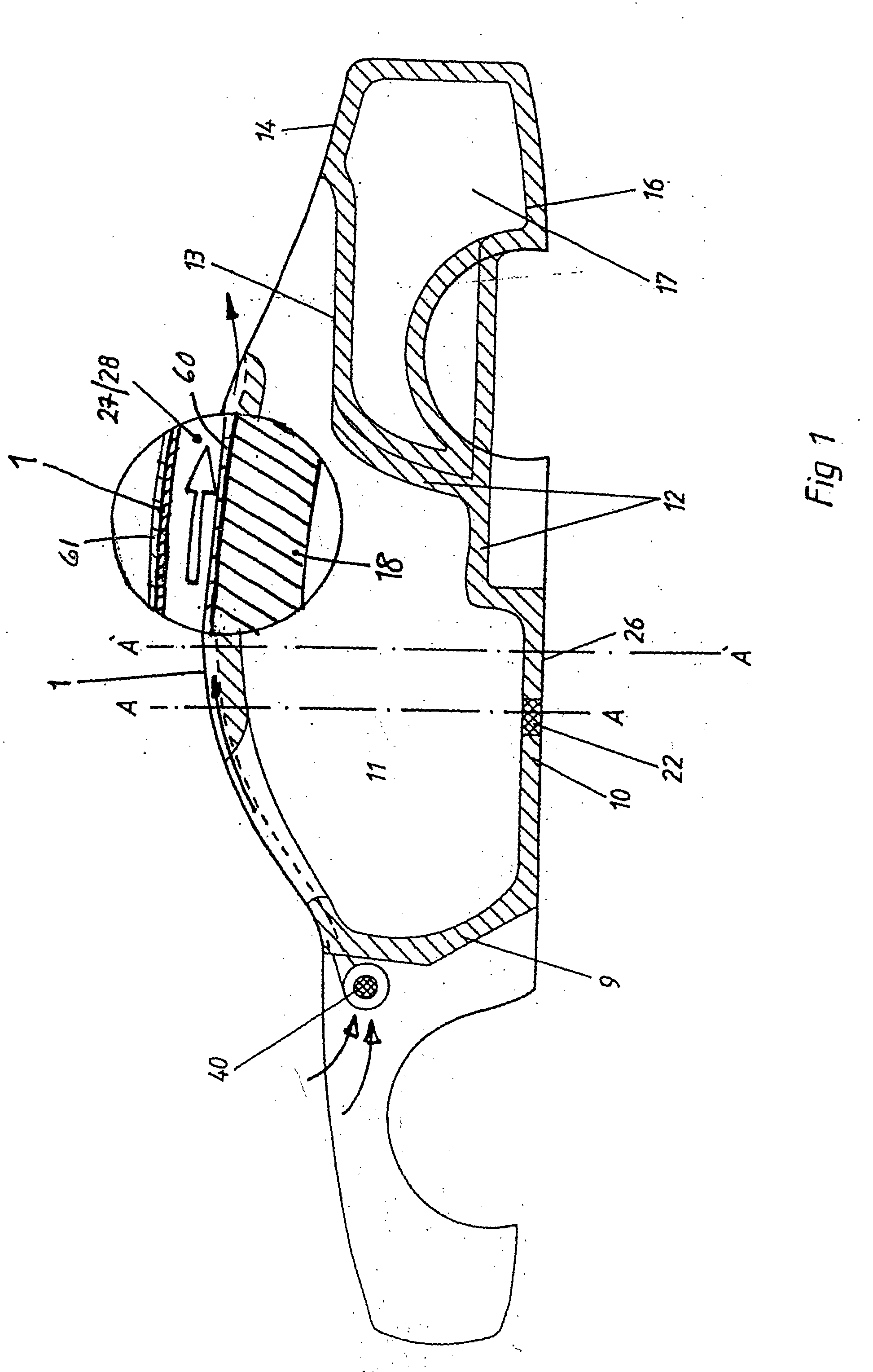
[0052] By their nature, thermal insulation bodies alone cannot lower the inside temperature of a vehicle below the outside temperature. Instead, the temperature in the passenger compartment will always be 2 to 5° C. above the outside temperature. If the outside temperature is, e.g., 20° C., the inside temperature of 22 to 25° C. will be within the “comfort range”. If the outside temperature is 30° C. on the other hand, a temperature of 32 to 35° C. will develop in a standing vehicle. As compared to non-thermally insulated vehicles, in which up to 70° C. will be reached in the standing vehicle, this is already significant progress. However this is not sufficient by today's standards. The layer thicknesses of insulation bodies are limited in vehicle construction for reasons of design. It is impractical to lower the inside temperatures to be within the “comfort range” in hot weather simply by selecting the thickness of the insulation bodies alone. Only the set of complementary measures...


PUM


Abstract

A body part of a vehicle, the body part having: an outer sheet that will form a part of the vehicle exterior surface; an inner part disposed between the outer sheet and the passenger compartment when the body part is assembled to the vehicle; a first infrared radiation reflecting layer on the outer surface of the outer sheet; and a second infrared radiation reflecting layer on the surface of the inner part that faces the outer sheet. The inner part includes a thermal insulation material. The outer sheet and the inner part delimit an air flow path for,supporting a flow of air adjacent the outer sheet and in the direction of the length of the vehicle. The air flow path is distributed transversely to the length of the vehicle for transporting heat convectively away from the vehicle.

Description

CROSS-REFERENCE TO RELATED APPLICATION [0001] This application is a Continuation-In-Part of pending U.S. application Ser. No. 10 / 435,027, filed May 12, 2003, itself a Continuation-In-Part of U.S. application Ser. No. 09 / 242,340, filed Feb. 12, 1999, now U.S. Pat. No. 6,561,562, issued on May 13, 2003, the disclosures of which are incorporated herein by reference.BACKGROUND OF THE INVENTION [0002] Efforts are being made in the motor vehicle industry, in particular in connection with passenger cars, to reduce fuel consumption and pollution. One approach to this objective is to reduce the weight of vehicles. [0003] Parallel with this, there is an ongoing effort to make vehicles safer, which often results in a weight increase because of additional components, for example the installation of transverse rails in the doors and struts in the vehicle cage. The resulting additional weight cannot even remotely be compensated by savings in the interior fittings. [0004] Because of the trend towa...

Claims


Application Information

Patent Timeline
Patent Type & Authority Applications(United States)
IPC IPC(8): B60J5/04B60R21/04
CPCB60R21/0428B60J5/0452
Inventor HESCH, ROLF
Owner MOLLERTECH GMBH
Why Eureka
Try Eureka