
Air blower apparatus

a blower and air technology, applied in the direction of heating types, heating types, magnetic circuit rotating parts, etc., can solve the problems of reducing the air blowing capability, reducing the air blowing capacity, and shortened fan length, so as to achieve further reduction of cost, increase vibration proofing ability, and increase the effect of cos

Inactive Publication Date: 2005-06-30
FUJITSU GENERAL LTD
View PDF21 Cites 45 Cited by
  • Summary
  • Abstract
  • Description
  • Claims
  • Application Information

AI Technical Summary

Benefits of technology

The present invention provides an air blower apparatus that can increase air blowing capability without increasing the size of the electronic motor. This is achieved by using an axial gap electronic motor with a rotor and stator, and attaching the air blowing fan to the rotor using a connecting means. The invention also includes various features such as the use of magnet coupling, the absence of an output shaft, the use of a bearing for pivotally supporting the stator, the use of a fan casing as a bracket for fixing the stator, the use of an elastic member, the use of a rotor as one end plate in the air blowing fan, the drip-proofing and dust-proofing treatment of the fan casing, the use of multiple core members connected in a ring shape, and the use of a bobbin-shaped insulator with core connecting means for connecting the adjacent core members to each other. These features improve the performance, cost, and assembly ability of the air blower apparatus.

Problems solved by technology

However, the above-described related art still has unsolved problems as described below.
However, if the axial lengths of the stator and rotor are increased, the length of the fan is shortened relatively, which reduces the air blowing capability.
However, if the magnetic flux density is made high, dust is liable to be attracted to the rotor magnet, which causes poor contact.
Also, when the stator is inserted for assembling, the stator collides with a fan casing or the rotor due to a magnetic attraction force, which may decrease the rotation accuracy or may cause initial failure.
Further, in the case of the air blower apparatus described in Patent Document 2, since the axial gap electronic motor of an air core inductor type is used, there arises a problem in that a high magnetic flux density is not obtained, and therefore a high output and high efficiency cannot be achieved.
Also, since a winding is arranged on a circuit board, and the circuit board is installed to the casing of equipment, the air blower apparatus is disadvantageous in terms of vibration and strength.

Method used


Image

  • Air blower apparatus
  • Air blower apparatus
  • Air blower apparatus

Examples


first embodiment

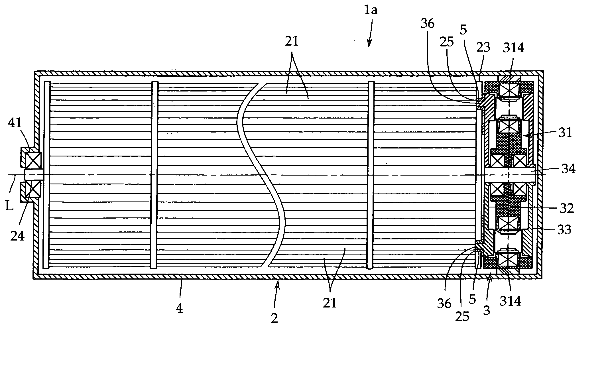
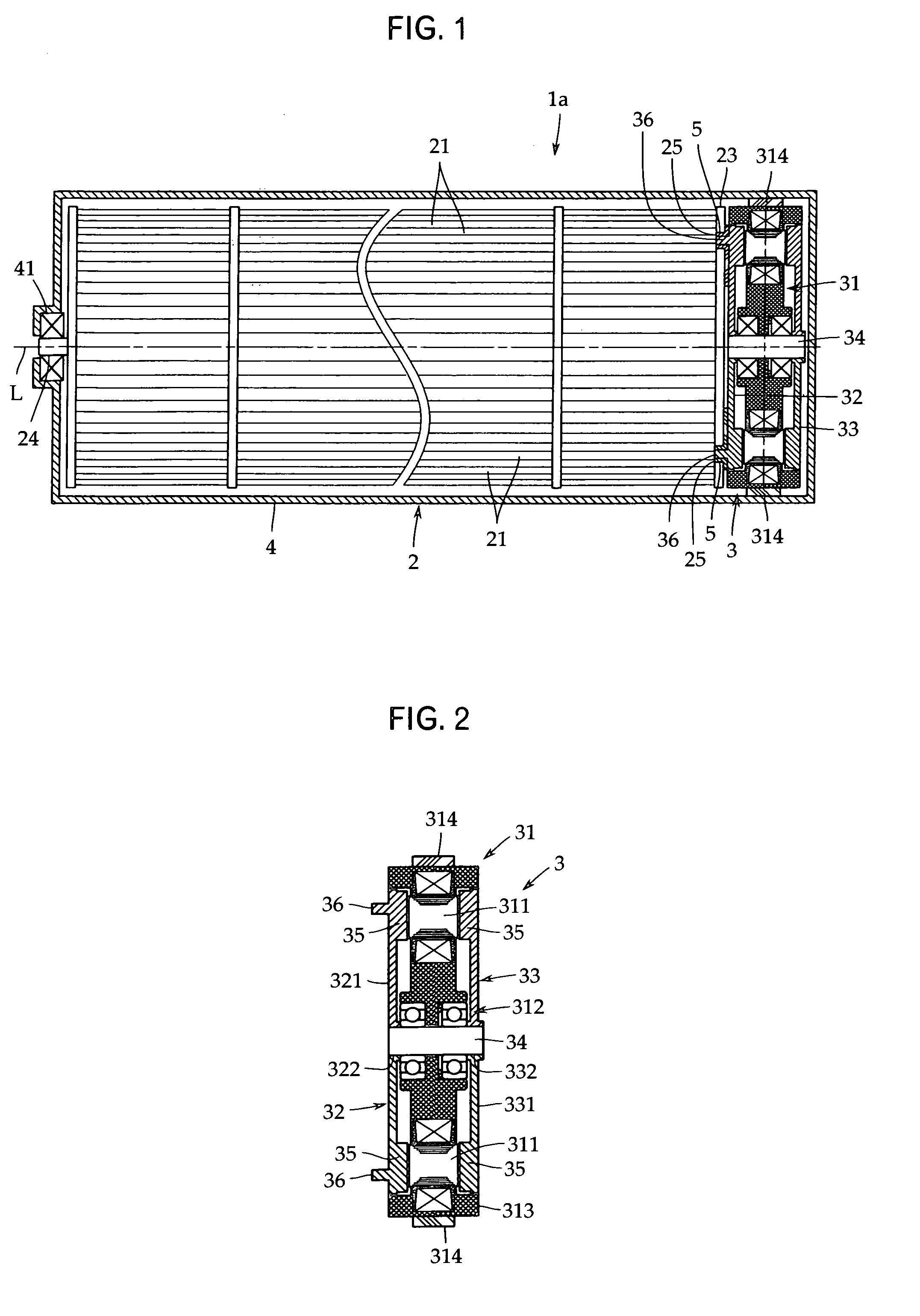
[0068] Although the air blowing fan 2 is installed to only one rotor 32 of the electronic motor 3 in the above-described first embodiment, the air blowing fan 2 may be installed to each of the rotors 32 and 33. Specifically, as shown in FIGS. 4 and 5, in an air blowing apparatus 1b, the electronic motor 3 is arranged in the center of the fan casing 4, and the air blowing fans 2, 2 are installed to the end surfaces of the rotors 32 and 33.

[0069] According to this configuration, two air blowing fans 2, 2 can be mounted to one electronic motor 3, so that not only the air blowing capacity can be increased, but also the rotation balance of the air blowing fans 2, 2 is good because the electronic motor 3 is arranged in the center. Such a mode is also embraced in the present invention.

[0070] Also, in the above-described embodiment, the air blowing fan 2 and the electronic motor 3 are connected to each other via the engagement means consisting of an irregular portion. However, in the case ...

second embodiment

[0075]FIG. 9 shows an air blower apparatus in accordance with the present invention. The feature of an air blower apparatus 1d is the bearing construction of the electronic motor 3. In this embodiment, the same reference numerals are applied to elements that are the same or regarded as the same as those in the above-described embodiment, and the explanation thereof is omitted.

[0076] The air blower apparatus 1d is an axial gap electronic motor in which the electronic motor 3 is provided projectingly with a boss 311a in the center on both sides of the stator 31, and the rotors 32 and 33 are supported via first and second bearings 311A, 311A each including a radial bearing, the connection shaft 34 rotating shaft) being not provided.

[0077] In this embodiment, the bearings 311A, 311A are configured so that the inner race of the radial bearing is fixed to the boss 311a of the stator 31, and the outer race thereof is fixed to the rotor side. However, the support positions of the inner rac...


PUM


Abstract

There is provided, at a low cost, an air blower apparatus capable of increasing the air blowing capability without an increase in size of an electronic motor, and having a high assembling ability. An electronic motor 3 is an axial gap electronic motor in which a rotor 32 and a stator 31 of the electronic motor are arranged opposedly with a predetermined gap along the rotation axis direction of the rotor, and coaxially supports an air blowing fan 2 on an attaching surface of the rotor 32 opposite to the stator.

Description

TECHNICAL FIELD [0001] The present invention relates to an air blower apparatus in which an electronic motor and an air blowing fan are integrated and, more particularly, to connecting means for connecting an electronic motor to an air blowing fan. BACKGROUND ART [0002] For the purposes of a smaller number of parts, more efficient assembling work, and the like, there has been used an air blower apparatus in which an electronic motor and an air blowing fan are assembled integrally in advance. This air blower apparatus is built in a system body such as an air conditioner as air blowing means, by which the whole of the system can be made smaller in size and lighter in weight and also the cost can be reduced. [0003] As one example of an air blower apparatus of this type, for example, Patent Document 1 (Japanese Patent Application Publication No. H10-117462) has disclosed an air blower apparatus in which a rotating shaft provided in an end portion of a line flow fan (Cross-flow fan) exte...

Claims


Application Information

Patent Timeline
Patent Type & Authority Applications(United States)
IPC IPC(8): F04D25/06F04D17/04F04D25/08F04D29/28F04D29/62F16F15/04F24F1/00H02K7/14H02K21/24
CPCF04D25/0653H02K21/24H02K7/14F04D17/04F04D29/28
Inventor KOJIMA, TOMONORIIGARASHI, HISAOFUJIOKA, TAKUSHITANABE, YOICHITERAKUBO, HIDETAKASHINOHARA, TAKAYUKIKASHIWAGI, TOMOHIROYAMADA, MASAKI
Owner FUJITSU GENERAL LTD
Learn More