Pre-amplifier for an optical communication

a technology of optical communication and amplifier, which is applied in the direction of amplifiers with semiconductor devices only, amplifiers with semiconductor devices, amplifiers, etc., can solve the problems of reducing the gain of the amplifier, and affecting the signal quality of the output signal

Active Publication Date: 2005-06-30
SUMITOMO ELECTRIC IND LTD
View PDF9 Cites 17 Cited by
  • Summary
  • Abstract
  • Description
  • Claims
  • Application Information

AI Technical Summary

Benefits of technology

[0020] At least one resistor and at least one circuit unit provided in the pre-amplifier may be connected in parallel to each other, or may be connected in serial to each other. Moreover, a variable resistor may be connected in serial to at least one resistor The variable resistor may be a transistor that has a control terminal and two current terminals with equivalent resistance therebetween. The equivalent resistance of the transistor may be varied by providing the control signal to the control terminal of the transistor.
[0021] The optical receiving of the present invention may further include a housing that has a stem and a die capacitor mounted on a center portion of the stem. The light-receiving device may be disposed on a substantially center of the stem via the die capacitor. The control signal may be provided from the control circuit that is disposed outside of the housing.
[0022] The stem may further provide a lead pin to provide the control signal to the other terminal of the light-receiving device and the control terminal of the pre-amplifier therethrough.
[0023] The optical receiver may further include a control buffer circuit within the housing. The control signal may be provided to the other terminal of the light-receiving device via the lead pin and to the control terminal of the pre-amplifier via the lead pin and the control buffer circuit.
[0024] The main amplifier of the present optical receiver may have a control terminal for inputting the control signal thereto. The control signal varies the frequency bandwidth of the main amplifier.
[0025] The main amplifier of the present invention may include a first circuit, a filter circuit and a second circuit. At least one of the first and the second circuits may have gain and the filter circuit may vary the cut-off frequency thereof by providing the control signal thereto. The filter circuit may include a circuit unit that has a switching device and a capacitor connected in serial to the switching device. The cut-off frequency of the filter circuit may be switched by providing the control signal to the switching device to conduct the capacitor.

Problems solved by technology

However, when the resistance of the feedback resistor Rf is large, saturation in the output signal may occur at the large signal current, which distorts the waveform of the output signal.
Further, when the single device receives optical signals each having different transmission speed, the light-receiving sensitivity is widely scattered.
Therefore, using the wideband amplifier, the gain of the amplifier must be reduced, accordingly, restricting the application of the amplifier.
However, to obtain an optimal frequency bandwidth of the pre-amplifier, it is insufficient to adjust the resistor R but requires to controlling the intrinsic gain A of the pre-amplifier.

Method used


Image

  • Pre-amplifier for an optical communication
  • Pre-amplifier for an optical communication
  • Pre-amplifier for an optical communication

Examples


first embodiment

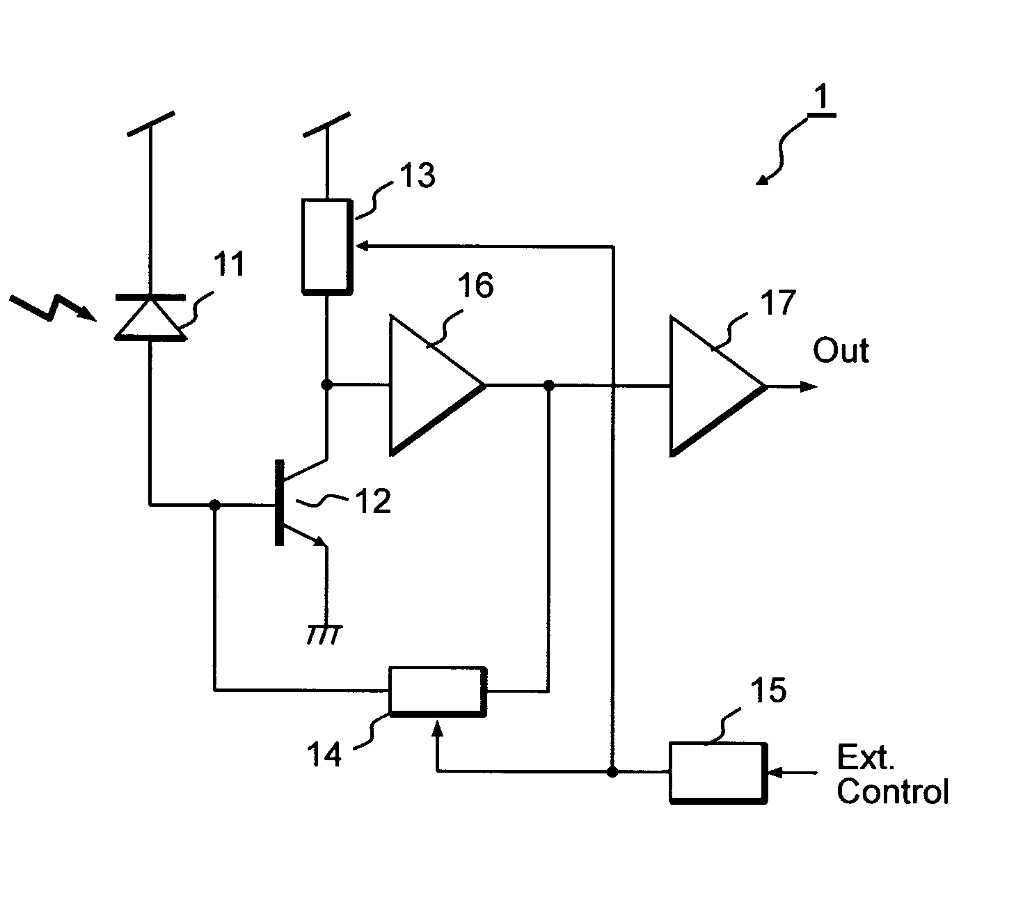
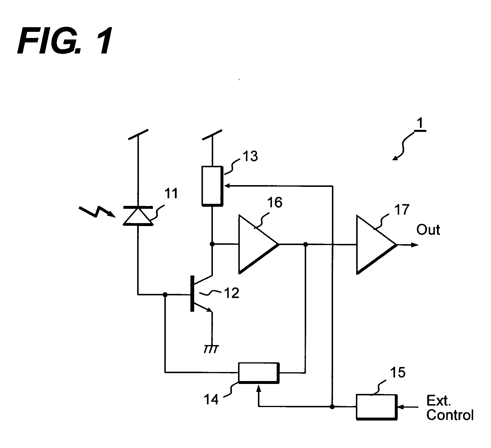
[0038]FIG. 1 shows a block diagram of a pre-amplifier 1 for the optical communication according to the present invention. The pre-amplifier 1 includes a transistor 12, which has a function of an inverting amplifier, a gain control circuit 13, a trans-impedance 14, a decoder 15, a level shifter 16, and an output buffer 17. This pre-amplifier, because of its intrinsic characteristic to convert an optical signal detected by a light-receiving device 11 to a corresponding electrical signal by current-to-voltage conversion, is used for the optical communication. The photo current generated by the light-receiving device 11 is input to the base of the transistor 12. The transistor 12 constitutes the gain control circuit 13 with a load resistance thereof and the gain control circuit decides the intrinsic gain of the pre-amplifier. The output of the gain control circuit 13 is adjusted in its level by the level shifter 16 to operate the trans-impedance 14. The output of the level shifter 16 is...

second embodiment

[0047]FIG. 3 explains a pre-amplifier 1a according to another embodiment of the present invention. This pre-amplifier 1a provides an output level detector 18 in addition to the elements involved in the previous pre-amplifier shown in FIG. 1. In this embodiment, the pre-amplifier 1a may be controlled in its gain and the bandwidth based on the signal detected by the output level detector 18 in addition to control of the gain control circuit 13a and the trans-impedance 14a by the information on the transmission speed.

[0048] The information on the transmission speed is simultaneously input to the gain control circuit 13a and the trans-impedance 14a, and the gain of the pre-amplifier and the trans-impedance may be varied in rough, while the output level detector 18 detects the output of the output buffer 17 and leads thus detected output level to the gain control circuit 13a and the trans-impedance 14a. The level detected by the output level detector 18 may be an average or a peak value...

third embodiment

[0058] Next, the third embodiment of the present invention will be described. FIG. 6 shows a block diagram of an optical receiver 1b according to the third embodiment. As shown in FIG. 6, the optical receiver 1b includes a control circuit 110, an optical fiber 120, a photodiode 130, a pre-amplifier 140, and a main amplifier 150.

[0059] The control circuit 110 outputs a bias signal to the photodiode 130 and the pre-amplifier 140 based on a control signal received outside of the optical receiver 1b. The control signal, when the optical receiver 1b has an interface to a host system, which is not shown in FIG. 6, such as a small form factor pluggable transceiver (SFP), may be a signal output from the host system. The control signal may include information on the transmission speed. Therefore, the control circuit 110 may output the bias signal corresponding to the transmission speed.

[0060] The photodiode 130 receives light output from the optical fiber 120 and converts the light into an...


PUM


Abstract

The present invention provides an optical receiver operable for optical signals each having different transmission speed. The optical receiver includes a light-receiving device, a pre-amplifier, a main amplifier, and a control circuit. The pre-amplifier, may be a trans-impedance amplifier, includes a parallel connection of a switching device and a resistor in a trans-impedance or a load element. By switching ON/OFF the switching device, the gain and the bandwidth of the pre-amplifier may be changed. By providing a filter circuit, whose cut-off frequency may be switched, in the main amplifier, the bandwidth of the optical receiver may be varied.

Description

BACKGROUND OF THE INVENTION [0001] 1. Filed of the Invention [0002] The present invention relates to a pre-amplifier used in an optical communication system, especially relates to a pre-amplifier having a trans-impedance configuration. [0003] 2. Related Prior Art [0004] In a light-receiving system used in the optical communication system, the pre-amplifier that converts an optical signal received by a light-receiving device into a voltage signal is necessary to have a low noise feature and a wide dynamic range. The trans-impedance amplifier is well known to satisfy such requests and is widely used in the optical communication system. Typical trans-impedance amplifier has a configuration that a feedback resistor is connected between the input and the output thereof, the impedance of which may be varied as the input power, thus the wide dynamic range may be obtained. A Japanese patent published as H09-232877 has disclosed such configuration of the trans-impedance amplifier. [0005]FIG....

Claims


Application Information

Patent Timeline
Patent Type & Authority Applications(United States)
IPC IPC(8): H03F3/08H03G3/30
CPCH03F3/08H03G3/3084H03F3/087
Inventor UESAKA, KATSUMINISHIYAMA, NAOKI
Owner SUMITOMO ELECTRIC IND LTD
Why Eureka
Try Eureka