Method and apparatus for key management in distributed sensor networks

Inactive Publication Date: 2005-06-30
MARYLAND UNIV OF
View PDF29 Cites 126 Cited by
  • Summary
  • Abstract
  • Description
  • Claims
  • Application Information

AI Technical Summary

Benefits of technology

[0013] It is therefore an object of the present invention to provide a key management scheme for Distributed Sensor Networks which relies upon probab

Problems solved by technology

Distributed sensor networks may be deployed in hostile areas where communication is monitored and nodes are subject to capture and surreptitious use by an adversary.
Both include arrays of sensor nodes that are battery powered, have limited computational capabilities and memory, and rely on intermittent wireless communication via radio frequency and, possibly, optical links.
These challenging operational requirements place equally challenging security constraints on DSN design.
The power, energy and the related computational and communication limitations of nodes in this range make it impractical to use typical asymmetric (public-key) cryptosystems to secure communications.
Traditional Internet style key exchange and key distribution protocols based on infrastructures using trusted third parties are impractical for large scale DSNs because of the unknown network topology prior to deployment, communication range limitations, intermittent sensor-node operation, and network dynamics.
However, traditional key pre-distribution offers two inadequate solutions: either a single mission key or a set of separate keys, each being pair-wise privately shared with another node, must be installed in every sensor node.
The single mission-key solu

Method used


Image

  • Method and apparatus for key management in distributed sensor networks
  • Method and apparatus for key management in distributed sensor networks
  • Method and apparatus for key management in distributed sensor networks

Examples


Embodiment Construction

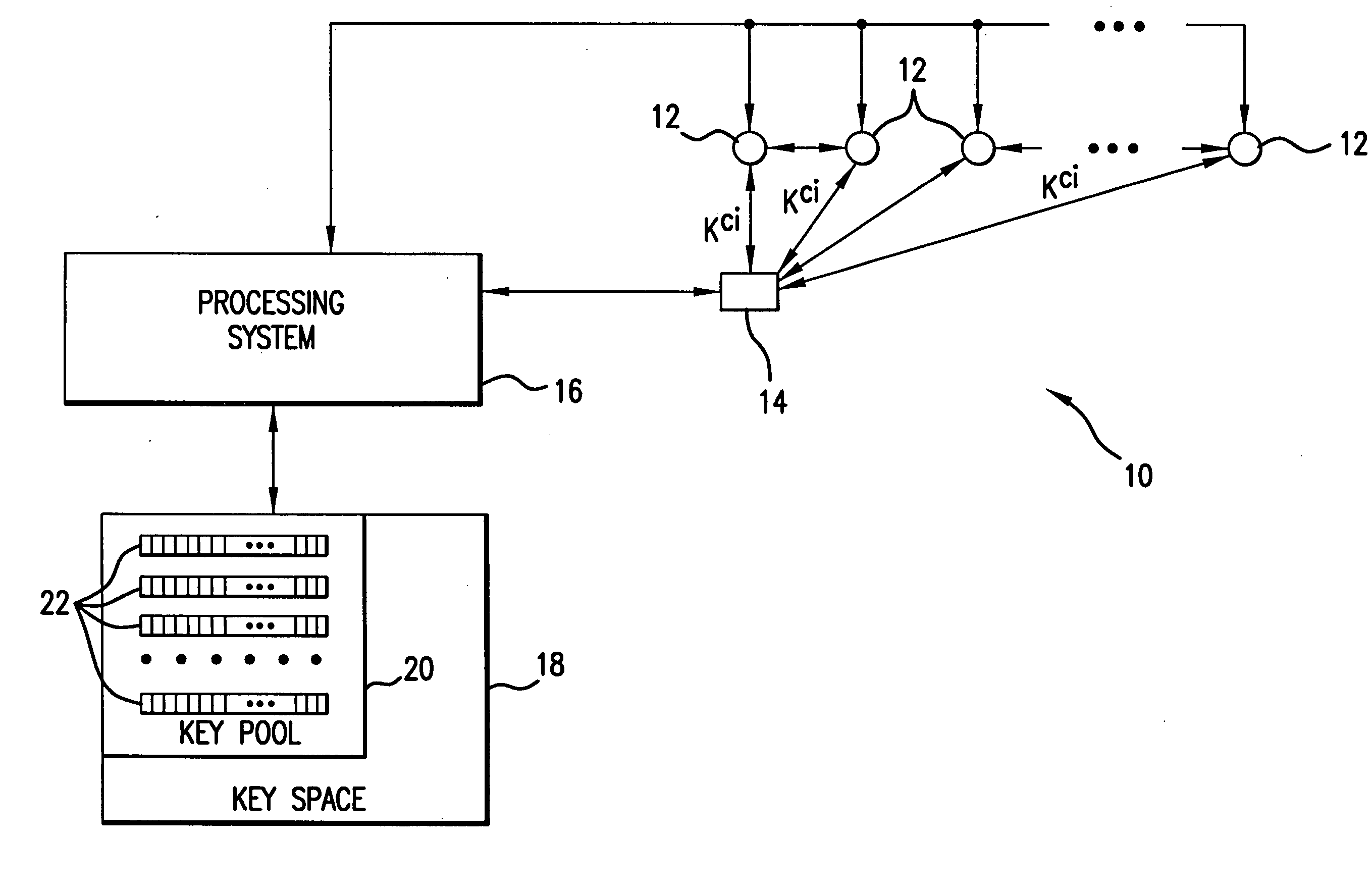
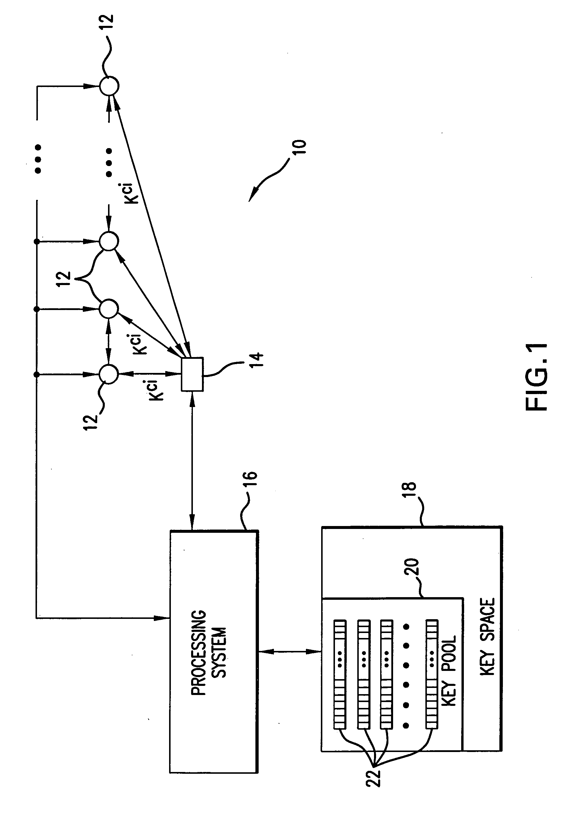
[0040] Referring to FIG. 1, a Distributed Sensor Network system 10 includes a plurality of sensor nodes 12 adapted for being deployed on a terrain under scrutiny for the purpose of real time traffic monitoring, security monitoring, military sensing and tracking, distributed measurement of phase connectivity, real-time pollution monitoring, wide light monitoring, wire tracking, etc. The DSN may include several thousands sensor nodes. Each sensor node has a low cost, limited in computation and information storage capacity, highly power constrained, and can communicate over a short range wireless network interface with other sensor nodes 12 or with controller nodes 14. The controller nodes 14 are equipped with sensor readers as well as adapted for bi-directional communication both with sensor nodes and the processing system which controls the functions and operations of the Distributed Sensor Network system 10. The controller nodes 14 are additionally equipped for performing broadcasti...


PUM


Abstract

In a distributed sensor network, a method of key management is carried out in several phases, particularly key pre-distribution phase, shared key discovery phase, and as needed, a path key establishment phase. In the key pre-distribution phase, prior to DSN deployment, a ring of keys is distributed to each sensor node, each key ring consisting of randomly chosen keys from a large pool of keys which is generated off-line. A shared key exists between each two key rings with a predetermined probability. In the shared key discovery phase, which takes place upon deployment of the DSN, every sensor node discovers its neighbors in wireless communication range with which it shares keys, and the topology of the sensor array is established by forming secure communication links between respective sensor nodes. The path key establishment phase assigns a path key to selected pairs of sensor nodes in wireless communication range that do not share a key but are connected by two or more links at the end of the shared key discovery phase. The key management scheme also assumes a revocation phase for removal of the key ring of the compromised sensor node from the network. Also, re-keying phase is assumed for removal of those keys with the expired lifetime.

Description

REFERENCE TO RELATED APPLICATIONS [0001] This Utility Patent Application is based on Provisional Patent Application No. 60 / 411,864 filed on 20 Sep. 2002.[0002] This invention was made with Government Support under Contract No. DAAD19-01-1-0494 and DAAD19-01-2-0011 awarded by U.S. Army Research Office / U.S. Army Research Laboratory. The Government has certain rights in the invention.FIELD OF THE INVENTION [0003] The present invention is related to distributed sensor networks, and more particularly, to cryptographic protection of communication associated with distributed sensor networks. [0004] In overall concept, the present invention relates to a key management scheme designed to satisfy both operational and security requirements of distributed sensor networks which includes selective distribution of keys to sensor nodes, sensor capture detection, key revocation and sensor disabling, as well as node re-keying without substantial computation and extended communication capabilities. [0...

Claims


Application Information

Patent Timeline
IPC IPC(8): G01C3/02H04L29/06
CPCH04L63/1408H04W12/02H04W76/02H04L2209/805H04L9/0838H04L9/0891H04W84/18H04W76/10H04W12/041H04W12/0433
Inventor ESCHENAUER, LAURENTGLIGOR, VIRGIL D.
Owner MARYLAND UNIV OF
Why Eureka
Try Eureka