Magnetic recording head for perpendicular recording, fabrication process, and magnetic disk storage apparatus mounting the magnetic head

a technology of perpendicular recording and recording head, which is applied in the direction of perpendicular magnetisation recording head, shielding head, etc., can solve the problems of significant restriction on the improvement of track density, insufficient recording magnetic field gradient which is important in the recording process together with the magnetic field intensity, and inability to increase the areal density. , to achieve the effect of improving the recording magnetic field gradient, suppressing the extension of the effective track width written to the magnetic medium, and maintaining the recording magneti

Inactive Publication Date: 2005-06-30
HITACHI GLOBAL STORAGE TECH NETHERLANDS BV
View PDF16 Cites 161 Cited by
  • Summary
  • Abstract
  • Description
  • Claims
  • Application Information

AI Technical Summary

Benefits of technology

[0017] By the provision of the trailing side shield adjacent with the main pole and defining the relation between the gap distance (Gt) on the trailing side and the gap distance (Gs) on the lateral side of the main pole as Gt<Gs, the recording magnetic field distribution in the cross-track direction can be improved while improving the recording magnetic field gradient and the extension of the effective track width written to the magnetic medium can be suppressed. Further, by defining the thickness (Gd) from the air bearing surface of the trailing side shield to less than throat height, or decreasing the Gd on the lateral side to less than that on the trailing side of the main pole, the recording magnetic field intensity can be maintained. Further, by setting the thickness (Gd) of the trailing side shield to the thickness described above only in the vicinity of the main pole and increasing the thickness for the portion away from the main pole, defoliation of the trailing side shield upon fabrication of the air bearing surface can be prevented.

Problems solved by technology

However, the current longitudinal recording system involves a problem that the areal density cannot be increased due to thermal fluctuation of magnetization of a magnetic medium as the recorded bit length is smaller.
However, as the track is made narrower, a problem that an effective track width to be written into a magnetic medium is larger than the geometric track width becomes conspicuous and this imposes a significant restriction on the improvement of the track density.
The documents described above state that a side shield is provided for controlling the track width to be written into a magnetic medium, but the gap distance on the trailing side is larger than the gap distance on the side, and the recording magnetic field gradient which is important in the recording process together with the magnetic field intensity is insufficient.
Further, while the magnetic field intensity decreases greatly when the side shield is provided, a structure for not decreasing the magnetic field intensity is insufficient.

Method used


Image

  • Magnetic recording head for perpendicular recording, fabrication process, and magnetic disk storage apparatus mounting the magnetic head
  • Magnetic recording head for perpendicular recording, fabrication process, and magnetic disk storage apparatus mounting the magnetic head
  • Magnetic recording head for perpendicular recording, fabrication process, and magnetic disk storage apparatus mounting the magnetic head

Examples


Embodiment Construction

[0038] Specific embodiments of the present invention are to be described with reference to the drawings. For the sake of easy understanding, identical components or features are described while attaching identical references throughout the drawings.

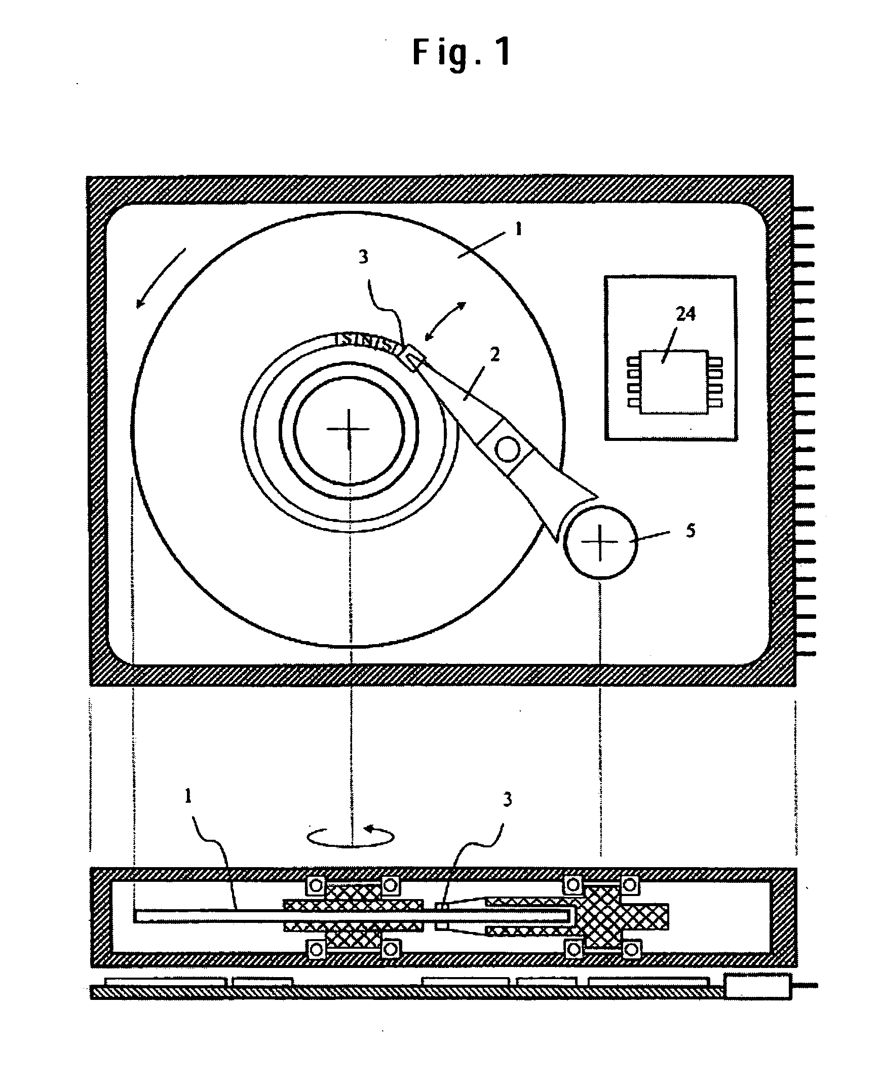
[0039]FIG. 1 is a schematic view of a magnetic recording and apparatus. In the magnetic recording and reading apparatus, magnetization signals are written and read by a magnetic head 3 fixed to the end of an arm 2 on a magnetic disk 1 driven rotationally by a motor. The arm 2 is driven in the radial direction of the disk by an actuator 5 and positioned on a written or read track. Writing signals for driving the magnetic head 3 or reading signals sent from the magnetic head are processed by a signal processing circuit 24.

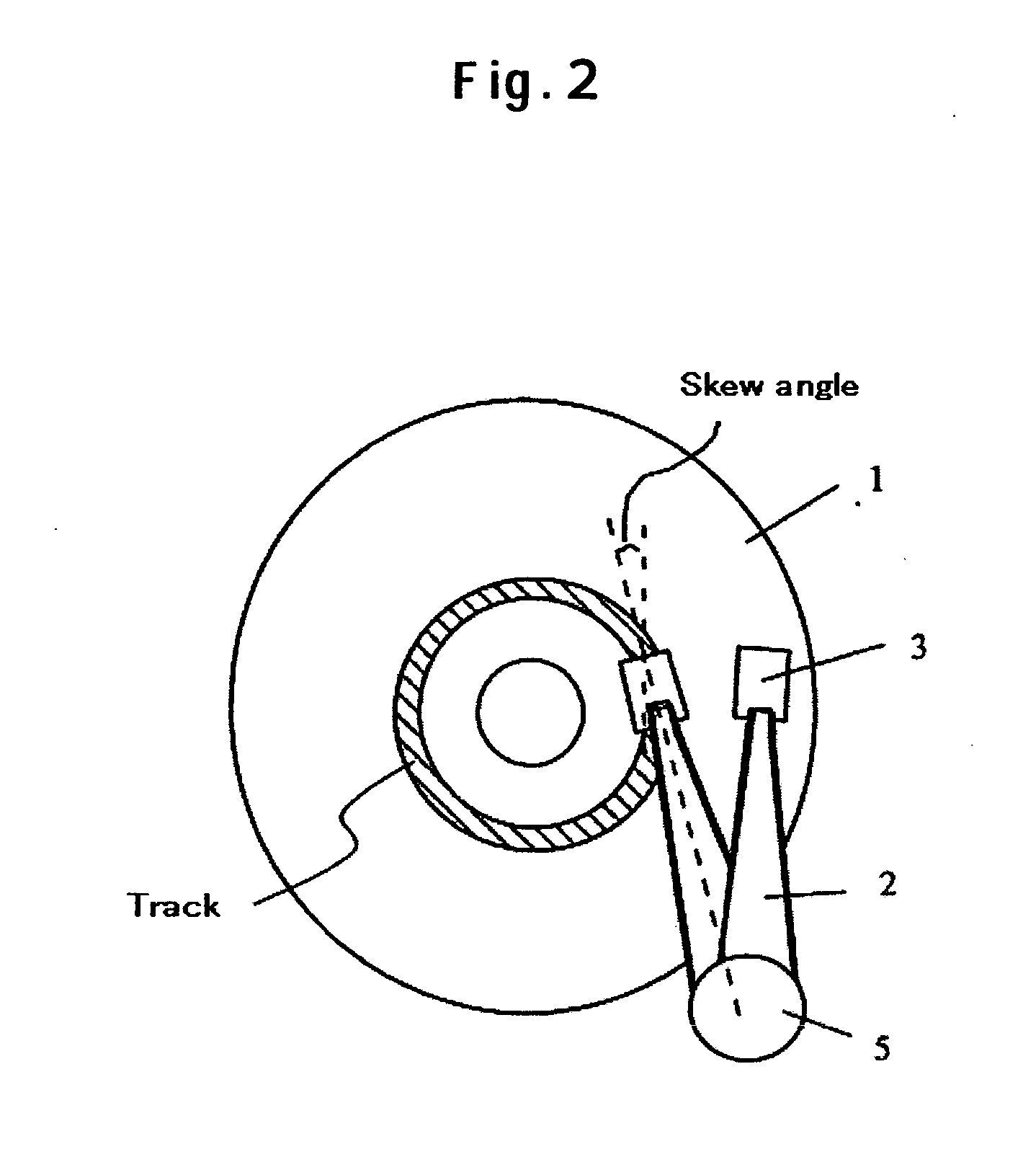
[0040]FIG. 2 shows a schematic view when the magnetic head 3 is moved by swinging the arm on the magnetic disk 1. In this case, a skew angle as shown in the drawing is formed. The range for the skew angle is about ±20°. ...


PUM

PropertyMeasurementUnit
heightaaaaaaaaaa
heightaaaaaaaaaa
gap distanceaaaaaaaaaa

Abstract

Embodiments of the invention provide a perpendicular magnetic writing head with a suppressed effective track width to be written on a magnetic medium while increasing writing magnetic field gradient. In one embodiment a trailing side shield is disposed by way of a gap film to a main pole of a perpendicular writing magnetic head. A gap distance (Gt) on a trailing side of the main pole and a gap distance (Gs) on a lateral side of the main pole is defined as Gt<Gt, and a thickness (Gd) from an air bearing surface of the shield is made equal to or less than a throat height. Alternatively, the thickness of Gd on the side of the main pole is reduced to less than that on the trailing side of the main pole. Further, for preventing defoliation of the shield upon fabrication of the air bearing surface, a thickness for a portion away from the main pole is increased.

Description

CROSS-REFERENCES TO RELATED APPLICATIONS [0001] This application claims priority from Japanese Patent Application No. JP-2003-427781, filed Dec. 24, 2003, the entire disclosure of which is incorporated herein by reference. BACKGROUND OF THE INVENTION [0002] The present invention relates to a magnetic head used for writing and reading to and from a magnetic recording medium and a magnetic recording apparatus mounting the magnetic head. [0003] In a magnetic disk apparatus, data on a recording medium is written and read by a magnetic head. For increasing the recording capacity of a magnetic disk per unit area, it is necessary to increase the areal density. However, the current longitudinal recording system involves a problem that the areal density cannot be increased due to thermal fluctuation of magnetization of a magnetic medium as the recorded bit length is smaller. A method capable of overcoming the problem includes a perpendicular recording method of recording magnetization signal...

Claims


Application Information

Patent Timeline
Patent Type & Authority Applications(United States)
IPC IPC(8): G11B5/31G11B5/11G11B5/127G11B5/147G11B5/187G11B5/23G11B5/39
CPCG11B5/11G11B5/315G11B5/1278G11B5/112
Inventor OKADA, TOMOHIRONUNOKAWA, ISAOMOCHIZUKI, MASAFUMI
Owner HITACHI GLOBAL STORAGE TECH NETHERLANDS BV
Why Eureka
Try Eureka